WIN Enterprises PL-80590 User Manual Download Page 31


www.win-ent.com 

30 

3.5 Boot Menu


Use the Boot Setup option as follows:


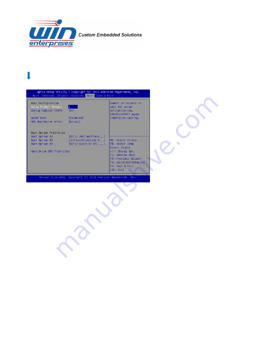
1.  Choose “Boot” from the main menu. The following screen appears:     


2. Move between items and select values by using the arrow keys. Modify the selected fields using 

the PnUP/PgDN Keys.    For information on the various options, press <F1> key.   


3. After you have finished with the Boot setup, press the <ESC> key to return to the main menu. 


Setup Prompt Timeout   

Number of seconds to wait for setup activation key. 65535(0xFFFF) means indefinite waiting.   


Bootup NumLock State 


Use this item to select the power-on state for the NumLock.   


Quiet Boot   

Enable or disable quiet boot option.   
 

Boot Option Priorities   

Set the system boot priority order.   


Summary of Contents for PL-80590

Page 1: ...www win ent com Network Appliance PL 80590 User s Manual Desktop Intel Atom Processor C2000 code name Rangeley Network System 8x Copper GbE LAN QuickAssist SATA CF and Mini PCIe...

Page 2: ...International Business Machine Corporation Award is a trademark of Award Software International Inc Intel is a trademark of Intel RTL is a trademark of Realtek VIA is a trademark of VIA Technologies I...

Page 3: ...fine 22 Chapter 3 BIOS Setup 23 3 1 Quick Setup 23 3 2 Entering the CMOS Setup Program 23 3 3 Menu Options 25 3 4 Advanced Menu 26 3 5 Boot Menu 30 3 6 Security Menu 31 3 7 Chipset Menu 32 3 8 Exit Me...

Page 4: ...k performance and maximum utilization In order to enhance network security performance the PL 80590 offers optional Intel Quick Assist technology that provides hardware level cryptographic acceleratio...

Page 5: ...One 4 pin power connector for HDD Storage Storage Storage Storage Compact Flash Socket one CompactFlash Type II USB Two external USB ports One internal 5x2 pin header Serial One RJ45 Console port COM...

Page 6: ...the PL 80590 if it is found to be damaged Note Keep the PL 80590 in the original packaging until you start installation Certification CE FCC PL PL PL PL 8059 8059 8059 8059A A A A Q17 Q17 Q17 Q17 Desk...

Page 7: ...ppliance Do not remove the anti static packing until you are ready to install the PL 80590 appliance Ground yourself before removing any system component from its protective anti static packaging To g...

Page 8: ...www win ent com 7 1 6 System Layout PL 80590 Front Side View PL 80590 Rear Side View...

Page 9: ...www win ent com 8 1 7 Board Dimensions...

Page 10: ...www win ent com 9 Chapter 2 Connector Jumper Configuration 2 1 Connector Jumper Locations and Definitions...

Page 11: ...ctor JP4 LAN3 LAN4 bypass select CN6 LCM connector JP5 LAN1 LAN2 bypass select CN7 Power on off GPIO Connector JP6 GPI or reset select CN8 KB MS Connector JP7 WDT LAN bypass select CN9 SPI Connector C...

Page 12: ...www win ent com 11 2 2 Connector and Jumper Settings CN1 COM2 connector CN2 SATA Power Pin Signal 1 DCD 2 RXD 3 TXD 4 DTR 5 Ground 6 DSR 7 RTS 8 CTS 9 RI 2 10 N A Pin Signal 1 12V 2 GND 3 GND 4 5V...

Page 13: ...om 12 CN7 SATA Connector CN7 GPIO Connector Pin Define Pin Define 1 3 3V 2 GND 3 GPIO30 4 GPIO31 5 GPIO32 6 GPIO33 7 GPIO34 8 GPIO35 9 GPIO36 10 GPIO37 Pin Signal 1 Ground 2 TXP 3 TXN 4 Ground 5 RXN 6...

Page 14: ...Header Pin Define Pin Define 1 KCLK 2 MCLK 3 KDAT 4 MDAT 5 N A 6 N A 7 PS2_GND 8 PS2_GND 9 PS2_VCC 10 PS2_VCC CN11 USB Connector Pin Define Pin Define 1 3 3V 2 AD0 3 AD1 4 AD2 5 AD3 6 Frame 7 PCIRST 8...

Page 15: ...ent com 14 CN12 LPC Connector CN13 GPI Connector Pin Define Pin Define 1 GPI0 2 GPI1 3 GPI2 4 GPI3 5 GND Pin Define Pin Define 1 3 3V 2 AD0 3 AD1 4 AD2 5 AD3 6 Frame 7 PCIRST 8 5V 9 CLOCK 10 N A 11 GN...

Page 16: ...15 GND 16 Reserved 17 Reserved 18 GND 19 Reserved 20 Reserved 21 GND 22 PERST 23 PERN0 24 3 3VAUX 25 PERP0 26 GND 27 GND 28 1 5V 29 GND 30 SMB_CLK 31 PETN0 32 SMB_DATA 33 PETP0 34 GND 35 GND 36 USB_D...

Page 17: ...www win ent com 16 CN19 Reset Connector Pin Define Pin Define 1 5V 2 DATA0 3 DATA0 4 GND 5 5V 6 DATA1 7 DATA1 8 GND RJ45 Console COM1 Pin Define 1 CTS 2 DTR 3 TXD 4 GND 5 GND 6 RXD 7 DSR 8 RTS...

Page 18: ...ector CN25 2 Pin Power Connector Pin Define 1 Ground 2 Reset Pin Define 1 MDI0 2 MDI0 3 MDI1 4 MDI2 5 MDI2 6 MDI1 7 MDI3 8 MDI3 D2 Link Activity LED Link Green Activity Blinking D1 Bi Color Speed LED...

Page 19: ...www win ent com 18 CN26 DC Jack Pin Define Pin Define 1 12V 2 GND Pin Define Pin Define 1 12V 2 GND Jumper Setting JP1 Clear CMOS Pin Setting 1 2 Normal Operation Default 2 3 Clear CMOS...

Page 20: ...ent com 19 Jumper Setting JP2 DDR power select 1 5V 1 35V Pin Setting 1 2 DDR Power 1 5V Default 2 3 DDR Power 1 35V Jumper Setting JP4 LAN3 LAN4 Bypass Pin Setting 1 2 Bypass mode 2 3 Disable mode De...

Page 21: ...www win ent com 20 Jumper Setting JP5 LAN1 LAN2 Bypass Pin Setting 1 2 Bypass mode 2 3 Disable mode Default Jumper Setting JP6 GPI or Reset select Pin Setting 1 2 GPI Input 2 3 Reset Default 22...

Page 22: ...www win ent com 21 Jumper Setting JP7 WDT LAN bypass select Pin Setting 1 2 WDT Default 2 3 LAN bypass 16...

Page 23: ...it provides users with much greater protection of the data than conventional magnetic disk device Pin Assignment Pin Assignment Pin Assignment Pin Assignment Pin Assignment 1 Ground 11 Ground 21 D00 3...

Page 24: ...ves The CMOS memory is maintained by a battery installed on the PL 80590 board By using the battery all memory in CMOS can be retained when the system power is switched off The system BIOS also suppor...

Page 25: ...n the AMI Flash program to update the system BIOS Run the CMOS Setup program after you turn on the system On screen instructions explain how to use the program Enter the CMOS Setup program s main menu...

Page 26: ...10 Save Changes and Exit to save your changes and reboot the system Choosing Discard Changes and Exit ignores your changes and exits the program Pressing ESC anywhere in the program returns you to the...

Page 27: ...Advanced Setup option as follows 1 Choose Advanced from the main menu The following screen appears 2 Use the arrow keys to move between fields Modify the selected field using the PgUP PgDN keys Some f...

Page 28: ...Configuration This sub menu shows the CPU related information which is automatically detected by BIOS 3 4 2 IDE Configuration This sub menu allow you to set or change the configurations for the IDE de...

Page 29: ...sub menu allows you to change the USB related features 3 4 4 Hardware Health Configuration This screen shows you the CPU core voltage System voltage System temperature and CPU temperature System Temp...

Page 30: ...hese read only fields show the functions of the hardware thermal sensor by CPU thermal diode that monitors the chip blocks to ensure a stable system Vcore 12V 5V 3 3V Show you the voltage of 12V 5V 3...

Page 31: ...Keys For information on the various options press F1 key 3 After you have finished with the Boot setup press the ESC key to return to the main menu Setup Prompt Timeout Number of seconds to wait for s...

Page 32: ...s and select values by using the arrow keys Modify the selected fields using the PgUP PgDN keys Please press the F1 key for information on the various options After you have finished with the Security...

Page 33: ...n from the Advanced menu The following screen appears 2 Move between items and select values by using the arrow keys Modify the selected field the PgUP PgDN keys For information on the various options...

Page 34: ...nd select values by using the arrow keys Modify the selected fields using the PgUP PgDN keys For information on the various options please press F1 key 3 Please press the ESC key to return the main me...

Page 35: ...Linux operating systems as follows Before installation please check your OS version If your OS is not in the following list please upgrade your OS version OS Version DOS DOS 6 22 Windows Windows 7 Ul...

Page 36: ...Cat 5 Cable 2M RoHS CB EC5200 00 1 Cross Over 2M Color RoHS CB CO5202 4 00 1 RJ45 to DB9 2M Cable RoHS CB RJDB91 00 1 Null modem cable 2M CB DB9200 01 1 KB MS cable 15CM CB IPS200 00 1 USB cable 25CM...

Reviews: