Wilton A3816 Operating Instructions & Parts Manual Download Page 6

6

A                               B                                  C

D                               E

General electrical cautions

The drill press  should be grounded in accordance
with the National Electrical Code and local codes
and ordinances. This work should be done by a
qualified electrician. The drill press should be
grounded to protect the user from electrical shock.

Wire sizes

Caution:

 for circuits which are far away from the

electrical service box, the wire size must be
increased in order to deliver ample voltage to the
motor. To minimize power losses and to prevent
motor overheating and burnout, the use of wire sizes
for branch circuits or electrical extension cords
according to the following table is recommended.

AWG (American wire gauge) number

Conductor length

240 volt lines

120 volt lines

0-50 feet

No. 14

No. 14

50-100 feet

No. 14

No. 12

Over 100 feet

No. 12

No. 8

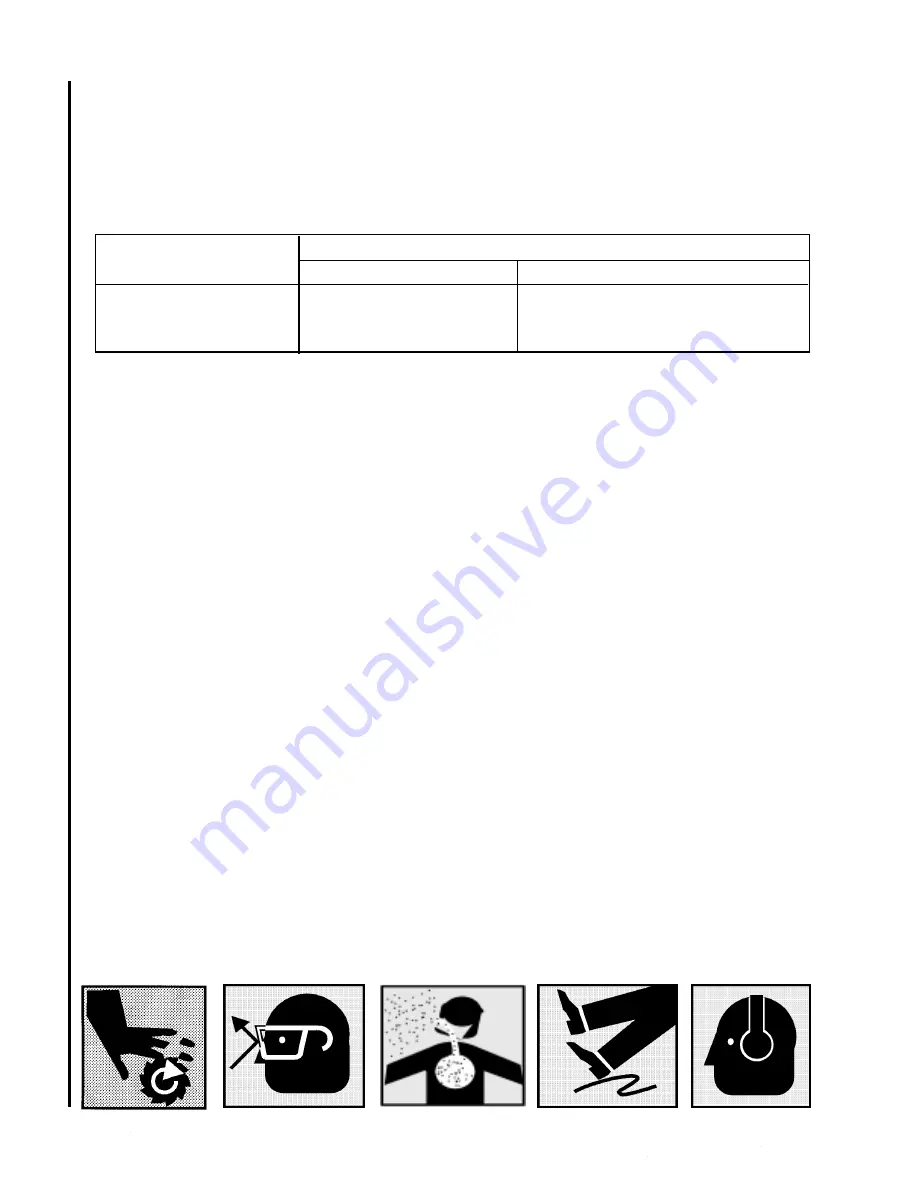
5.  Keep hands in sight.  Do not put hands or fingers
around, on, or below any rotating cutting tools.
Leather safety gloves should be used when handling
any sharp objects or cutting tools.  See Figure A.

6.  Always wear protective eye wear when operating,
servicing or adjusting machinery.  Eyewear shall be
impact resistant, protective safety glasses with side
shields complying with ANSI Z87.1 specifications.
Use of the eye wear which does not comply with
ANSI Z87.1 specifications could result in severe
injury from breakage of eye protection. See Figure
B.

7.  When drilling in material which causes dust, a
dust mask shall be worn.  See Figure C.

8.  Avoid contact with coolant, especially guarding
the eyes.

9.  Non-slip footwear and safety shoes are recom-
mended.  See Figure D.

10.  Wear ear protectors (plugs or muffs) during
extended periods of operation.  See Figure E.

Safety Instructions for Drill
Presses

1.  All work shall be secured using either clamps or a
vise to the drill press table.  It is unsafe to use your
hands to hold any workpiece being drilled.

2.  Drill press head and table shall be securely
locked to the column before operating the drill press.
This must always be checked prior to starting the
machine.

3.  Always use the correct tooling.  Tooling shall
always be maintained and properly sharpened.  All
tooling must be run at the proper speeds and feeds
as they apply to the job.  Use only recommended
accessories and follow those manufacturers instruc-
tions pertaining to them.  Tooling shall be not be
forced in to any workpiece but fed according to the
proper specifications.  Failure to follow these instruc-
tions will not only ruin the tooling as well as the
machine, but can cause serious injury.

4.  Never brush away any chips while the machine is
in operation.  All clean up should be done when the
machine is stopped.

Summary of Contents for A3816

Page 1: ...s Parts Manual 15 Inch Vari Speed Drill Press Models A5816 A5818 A3816 A3818 Manufactured after Serial No 807137 Part No 5507564 Revision B6 WMH Tool Group Inc 2420 Vantage Dr Elgin IL 60123 Ph 847 649 3010 Fax 847 851 1144 ...

Page 2: ......

Page 3: ...3 Table of Contents Cover Page 1 General Specifications 4 Operating Precautions 5 Set up and Operation 7 Maintenance 9 Wiring Diagrams 10 Troubleshooting 11 Replacement Parts 12 ...

Page 4: ...odel Bench Model Bench Model Motor Motor Speed rpm 1 725 rpm 1 725 rpm 1 725 rpm 1 725 rpm HP 1 HP 3 HP 1 HP 3 HP Power Rating 1 Ph 115 220V 3 Ph 220 440V 1 Ph 115 220V 3 Ph 220 440V Spindle speed rpm 400 to 5 000rpm 400 to 5 000 rpm 400 to 5 000 rpm 400 to 5 000rpm Capacity Cast iron up to 5 8 in up to 5 8 in up to 5 8 in up to 5 8 in Steel up to 1 2 in up to 1 2 in up to 1 2 in up to 1 2 in Dril...

Page 5: ...which can get caught in moving parts Rubber soled footwear is recommended for best footing 3 Do not overreach Failure to maintain proper working position can cause you to fall into the machine or cause your clothing to get caught pulling you into the machine 4 Keep guards in place and in proper working order Do not operate the machine with guards removed 5 Avoid dangerous working environments Do n...

Page 6: ...he eye wear which does not comply with ANSI Z87 1 specifications could result in severe injury from breakage of eye protection See Figure B 7 When drilling in material which causes dust a dust mask shall be worn See Figure C 8 Avoid contact with coolant especially guarding the eyes 9 Non slip footwear and safety shoes are recom mended See Figure D 10 Wear ear protectors plugs or muffs during exten...

Page 7: ...factory No further lubrication is required at the time of installation Electrical Connection Refer to the Wiring Diagram section for wiring information Connection to electrical power should be made by a qualified electrician Observe local electrical codes when connecting the machine The motor should be protected with a time delay fuse or circuit breaker with a amperage rating slightly higher than ...

Page 8: ...rill is usually measured in terms of the rate at which the outer periphery of the tool moves in relation to the work being drilled The common term for this is Surface Feet per Minute SFM The relationship of SFM is expressed in the following formulas SFM 0 26 X rpm X Drill Diameter in inches RPM 3 8 x ________SFM__________ Drill diameter in inches In general the higher the speed the shorter the dri...

Page 9: ...THAL VOLTAGE LEVELS 1 Start drill press Set speed control to highest speed Stop drill press 2 Disconnect electrical power to drill press 3 Remove head cover 4 Remove belt With speed control setting at the highest speed the belt should be loose enough to remove 5 Install the replacement belt Install the head cover 6 Connect electrical power to the drill press 7 Operate the drill press to verify cor...

Page 10: ...to accommodate the drilling of a hole that may be offset from the center of the table Reposition the drill head by loosening the locking handles and swinging the drill head to the desired position Then retighten the locking handles Wiring Diagrams Refer to Figure 5 for wiring information The drive motor is115 230 volt single phase or 220 440 volt three phase Notice When converting machine voltage ...

Page 11: ...ot hold downs are tight and that table lock and drill head bolts are tight 3 Speed too fast for material and drill size 3 Check spindle speed recom mendations Reduce speed if necessary 4 Feed too fast for material and drill size 4 Reduce feed rate 5 No or improper cutting fluid or coolant 5 Use cutting fluid or change to being used proper fluid or coolant for material being drilled 6 Improperly gr...

Page 12: ... The item numbers shown on the illustration relate to the item number on the facing page of the parts listing Order replacement parts from Wilton Corporation 300 South Hicks Road Palatine IL 60067 TEL 1 888 594 5866 FAX 1 800 626 9676 Identify the replacement part by the part number shown in the parts listing Be sure to include the model number and serial number of your machine when ordering repla...

Page 13: ...13 Exploded View Head Models A5816 A5818 A5836 A5838 70A 99 Note 1 21 17A 17 39 ...

Page 14: ...ith Key 1 2A 5507495 2 MT x JT3 Arbor 1 3A 5507496 Spindle Assembly 1 4 5053070 Quill Band 1 5 9010541 O Ring 1 6 9054511 Set Screw 2 5 16 18 x 3 8 7 5032611 Bearing Retainer 1 8 9100331 Bearing 2 9 5041010 Quill 1 10 9058561 Wavy Spring Washer 1 11 9074081 Truarc Retainer 1 13 9056981 Hex Jam Nut 3 1 4 20 16 5518170 Sloted self taping Screw 5 3 16 24 x 3 8 17 5518157 Power Cord 1 Phase 1 17A 5517...

Page 15: ...15 Exploded View Head Models A3816 A3818 A3836 A3838 A ...

Page 16: ...44 9052191 Socket Set Screw 4 5 16 18 x 1 2 45 5032781 Motor Plate Bar 4 46 9057111 Whiz Flange Locknut 4 48 9056171 Carriage Bolt 4 5 16 18 x 1 1 2 49 9058051 Split Lock Washer 1 2 ID 4 50 9056841 Hex Nut 1 2 13 4 51 5518161 Step Pulley Motor 1 52 5518162 Socket Set Screw 2 1 4 20 x 5 16 53 5042011 Key Motor 1 54 5518163 Drive Belt 1 55 5518164 Step Pulley Spindle 1 55A 5518165 Spindle Pulley Sha...

Page 17: ...17 Exploded View Base Floor Models A5816 A5818 A3816 A3818 11 8 10 5 6 23 22 7 9 19 21 20 18 12 13 14 15 16 17 4 3 2 1 25 ...

Page 18: ...507510 Standard Column 1 5511850 Short Column 1 10 5507511 Flange Base Column 1 11 5630771 HHCS 1 2 12 x 1 1 2 4 12 5507571 Cover Plate 1 13 5507570 Bushing 1 14 5507513 Worm Table Raiser 1 15 5507514 Gear Table Raiser 1 16 5507515 Shaft Table Raiser 1 17 5507516 C Ring Table Raiser 2 18 TS 0050051 SHCS 1 4 x 1 4 19 5507518 Socket Head Set Screw 1 5 16 18 x 3 8 20 5507519 Crank Table Raiser 1 21 5...

Page 19: ......

Page 20: ...WMH Tool Group Inc 2420 Vantage Dr Elgin IL 60123 Ph 847 649 3010 Fax 847 851 1144 ...

Reviews: