


pump casing should be swivelled on the spacer through an
angle of 180° (or 90°) (See Fig. 2).
The centreline of the electric motor must always be horizon-
tal.
5.2 Hydraulic connections
– Direct connection to pipe with threaded fitting by means of
unions (not supplied).
– Position the pump on a vertical or horizontal pipe and
provide for isolating valves on either side to make dismant
-
ling easier.
– A check valve should be installed on the discharge side for
domestic hot water distribution applications.
– Check that the pipes are correctly aligned to avoid any clam
-
ping on the appliance.
5.3 Electrical connections
Electrical connections and checks must be made by
an approved electrician in compliance with the ap
-
plicable local standards.
Check that the terminal box is accessible and protected from
any hazards due to water (leaks, splashes or condensation,
etc.).
– Make sure that the characteristics of the electric current and
the available voltage comply with the information marked on
the appliance's identification plate.
– Use a cable that complies with the applicable local standards.
– Protection of the motor by circuit breaker (See Fig. 4).
Any incorrect electrical connection will lead to da
-
mage to the motor. The cable must be protected from
any dampness and must never come into contact
with the piping or with the pump.
–
SINGLE-PHASE:
Cable 3 x 0.75 mm
2
(max. 3 x 2.5 mm
2
)
(2 earth)
–
3-PHASE:
Cable 4 x 0.75 mm
2
(max. 4 x 2.5 mm
2
)
(3 earth)
Connection to mains (See Fig. 3 Motor terminal box and 4
Motor protection circuit breaker)
DO NOT FORGET TO EARTH.
6. Starting up
6.1 Filling - Degassing
Never operate the pump when dry, even for a
short time.
– Open the isolating valves on the suction and discharge sides
of the pump. Completely fill the system.
– Bleed to remove air.
6. 2 Check on direction of rotation
– Check the direction of rotation of pumps equipped with a 3
-
phase motor by supplying a short pulse of electric power. The
direction of rotation must comply with the information speci
-
fied on the identification plate. If it does not, invert the two
phase wires in the motor terminal block.
– Check the current draw.
– Adjust the magnetothermal protection device to the current
specified on the motor identification plate.
7. Maintenance
No specific maintenance is required during operation.
Keep the pump scrupulously clean.
The bearings are life
-
lubricated in accordance with the motor's
service life.
During the initial mechanical seal bedding period, there may
be slight leaks. These leaks will disappear after a few hours
in operation.
After shutdown for a long period, check that:
– the circuit and the pump are correctly filled,
– air bleeding operations have been carried out,
– the shaft rotates freely without any friction points.
If the mechanical packing is replaced, it is man
-
datory to disconnect the whole assembly from
the piping BEFORE disassembling the motor
from the hydraulic casing.
ATTENTION!
ATTENTION!
ENGLISH
9
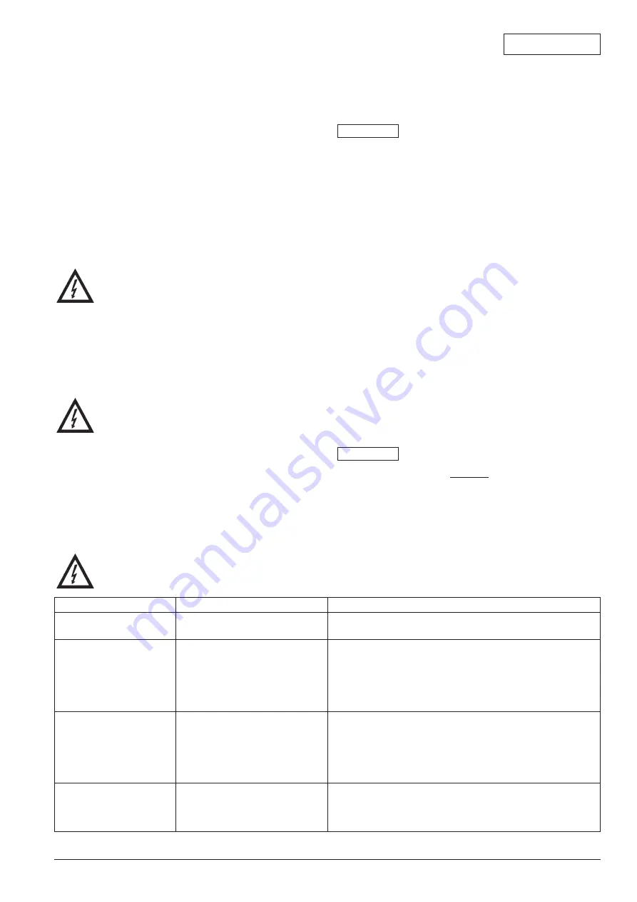
Failures
Causes
Remedial action
The pump will not start
a) The motor will not start
a) Check that electric current is present on the motor terminals
b) The motor has „burned out“
b) Replace it
No output from pump
a) Inernal components are
a) Dismantle the pump and clean it
blocked by foreign bodies
b) Pump turns in the wrong
b) Invert the direction of rotation by inverting the two wires on
direction
the motor terminal block (if 3
-
phases)
c) Valve closed in discharge
c) Check and open the valve
side
Pump output is too low
a) Valve partly open on discharge
a) Open the valve gradually and completely until the pressure
(or pressure is insufficient)
side
is stabilized
b) Considerable head losses
b) Check the head loss again. (Replace the pipes with other
pipes with larger diameter)
c) Suction pipe partially blocked
c) Check the pipe. Clean
or clogged
Oberheading of motor
a) Rotation difficult
a) Check that it is possible to turn the motor by hand
(screw or priming slot on back of motor.
b) Incorrect supply voltage
b) Check that the voltage on the motor terminals is within
the standard tolerances
8. Operating failures
Prior to maintenance or repair work, turn off
the pump and ensure that it is not turned on by
unauthorised personnel.
If the fault cannot be remedied, please contact your local plumbing and heating specialist or WILO customer services.


