12
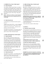
Table 3 Drive Fault Codes
ERROR CODE
BOOSTER BEHAVIOUR
TROUBLESHOOT
E011 DRY RUN
The controller starts the pump every
30 minutes over 24 hours. If dry
running remains, it switches off the
pump.
Check the hydraulic supply.
If a set point pressure higher than the
pressure the pump can deliver is pro-
grammed, the controller will consider it
as dry running.
E021 OVERLOAD
After the alarm detection the control-
ler will try 4 times to
Check that the rotor is not locked.
start the pump. After these 4 trials
the pump is switched off.
Check the state of the fuses..
Check the input data in the controller
E025 DISCONNECT MOTOR
Motor will not start.
Check the motor winding.
Check the supply cables.
Check that the Imax is not set to off in
the menu (Table 2)
E040 P SENSOR DEFFECT
The controller stops.
Contact the technical service depart-
ment.
E031 OVER T°
If the temperature is too high, the
controller will stop the motor from
running.
Check that the water temperature does
not exceed 40°C.
Check that the ambient temperature
does not exceed 50°C.
E023 SHT CIRCUIT
After the alarm detection the
controller will try 4 times to start the
pump. After these 4 trials the pump is
switched off.
Check the motor connections and wind-
ings. If the problem remains contact the
manufacturer.
E071 EEPROM
If the controller detects a defect on
its internal memory this error will be
displayed.
Contact the technical service depart-
ment.
E005 HIGH VOLTAGE
If the controller detects an overvolt-
age, it stops over some seconds and
then starts again.
Check the controller supply voltage.
E004
If the controller detects an under
voltage, it stops the pumps.
Check the controller supply voltage.
LOW VOLTAGE
[WHITE SCREEN]
No function and nothing on the
screen.
Check the controller supply voltage and
circuit breakers in (Fig 1).
Check the 20A fuses
Summary of Contents for 2819142
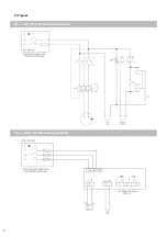
Page 6: ...6 Fig 1 MHI PS EM Electrical Connections Fig 2 MHIE DM Electrical Connections 8 Figures...
Page 7: ...7 Fig 3 MHI EC EM Fig 4 MHIE EM Electrical Connections...
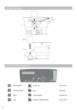
Page 8: ...8 Fig 5 General Arrangement Hydraulic Fig 6 PS EM Layout...
Page 9: ...9 Fig 7 MHIE EM DM Layout Fig 8 MHIE EM Controls...
Page 16: ......


