Chapter 1
Overview
The front and rear panels
4460 GSM System Option and 4468 EDGE System Option
Version 12.20
7
Front panel
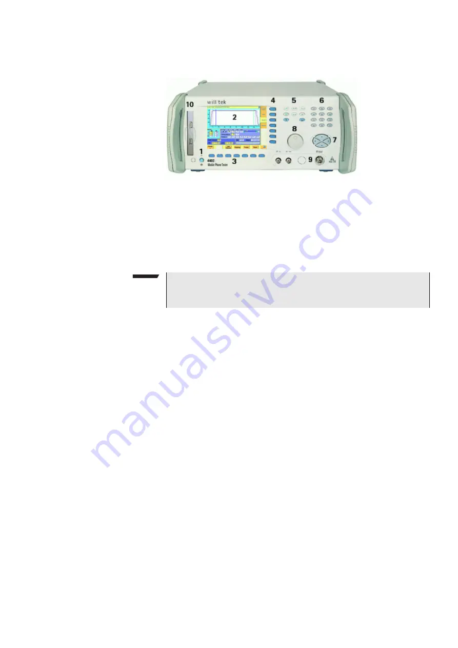
The front panel of the 4400 is divided into ten sections.
Section 1 – On button and MS Power connector
When you bring the power switch on the rear panel of the 4400 in its
I
position,
the unit goes to standby mode and the indicator just underneath the
On
button
is backlit in red.
Push the
On
button to switch the 4400 into operating mode. The indicator will
then turn green.
When you push the
On
button again, the 4400 will go back into standby mode.
The MS Power connector is used in conjunction with the MS Power Supply and
Current Measurement Options. It provides supply voltage and current for the
mobile under test.
The cable for this connector is delivered with the MS Power Supply Option.
Section 2 – Display
The display is the graphical user interface of the 4400. It will show you menus
with entry fields and display fields. The display also labels the software-driven
softkeys (see section 3) and marker tabs (see section 4).
Section 3 – Softkeys
Softkeys call specific functions that vary with the menu displayed. For instance,
when you switch on the 4400, the softkeys will allow you to select the option
you want to work with (e.g. call mode or non-call mode).
Section 4 – Marker tabs
Section 5 – Function keys
Function keys are used for general operation. They have a fixed function. The
E
NTER
key, for instance, confirms changes on entry fields.
NOTE
The power switch is located on the rear panel of the 4400. A dark standby
button indicates that the 4400 is not connected to mains.


