background image

PMP-112 Multiposition 

Oil Furnaces

 – 

Furnace Manual


6


11/13 

1.6.1


Masonry chimney 

This furnace can be vented into an existing masonry chimney. 
However, the unit must not be vented into a chimney into which a 
solid fuel burning furnace is already being vented. 
Before venting this furnace into a chimney, its condition must be 
checked and repairs made, if necessary. Also, the chimney lining 
and dimensions must conform to local and national codes. 

1.6.2


Factory Built Chimneys 

Oil fired furnaces are approved for use with “L” type vents. The unit 
may also be used with an approved chimney of proper dimensions 
and temperature ratings as specified in the installation code. Refer 
to chimney manufacturer’s instructions for proper installation. 

1.6.3


Draft Regulator 

It is recommended that a draft regulator be installed in cases where 
the draft is either high or variable due to external conditions. Follow 
the instructions provided with the regulator. 

1.6.4


Side-wall Venting 

The heating unit is approved for side-wall venting. This system is 
comprised of a model VTK-54 side-wall venter and a 4” insulated 
vent pipe, model IFV-410, IFV-420. Refer to the installation 
instructions provided with the venting system. 

1.7


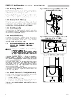
BLOCKED VENT SHUT-OFF DEVICE 

(BVSO) FOR CHIMNEY VENTING - 

OPTIONAL 

It is imperative that this device be installed by a 
qualified service technician. 
A positive pressure venting system (Sealed 
Combustion System or Direct Vent) must NOT use 
the BVSO. Follow the instructions supplied with 
the venting system. 

This device is designed to detect the insufficient evacuation of 
combustion gases in the event of a vent blockage. In such a case 
the thermal switch will shut down the oil burner. The device will then 
need to be re-armed MANUALLY. 
Refer to the detailed instructions and wiring diagrams supplied with 
the BVSO for the installation and wiring procedures. The length of 
wires supplied with the unit is such that the safety device must be 
installed between the flue outlet of the appliance and the draft 
regulator, as indicated in the instructions. 
It is also essential that the BVSO be maintained annually. For more 
details refer to the instructions supplied with the device itself, as well 
as Section 2 of this Manual. 

1.7.1


BVSO Performance Test (If Installed) 

The purpose of the following test is to check that the electrical outlet 
on the furnace, designated to the BVSO, is functional. 
1. 

Start up the burner; 

2. 

Disconnect one wire of the BVSO; 

3. 

The burner must shut-off immediately, while the blower 
continues to run to the end of the cool-down cycle. 

If the test is not in line with the above, call a QUALIFIED SERVICE 
TECHNICIAN. 

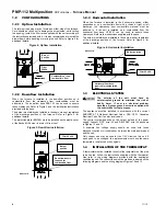
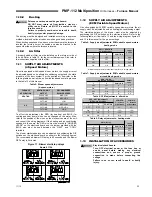
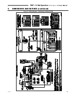
Figure 8: BVSO mounting installation: Upflow with 

vertical exhaust (OPTIONAL) 


Figure 9: BVSO mounting installation: Upflow with 

horizontal exhaust (OPTIONAL) 


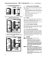
Figure 10: BVSO Wiring (OPTIONAL) 


Summary of Contents for PMP-112

Page 1: ...ller service technician Failure to comply could result in severe personal injury death or substantial property damage When calling or writing about the furnace Please indicate furnace model number and serial number from rating label You may list the serial number and model number in the space provided on the Installation and service certificate found on page 16 If your furnace is shut down during ...

Page 2: ...lbows 20 Always connect and seal a return air duct to the furnace unless the furnace is located in a large space such as an unpartitioned basement Route the return air duct to an adjacent room if no return air manifold is used 21 Install furnace maintaining minimum clearances for service and separation from combustible surfaces described in this manual 22 Install start up service and maintain burn...

Page 3: ...ents from water Outdoor installation will lead to a hazardous electrical condition and to premature failure of the equipment The minimum clearances from combustible material for each of the positions are specified in Table 1 If the furnace is installed in a basement or on a dirt floor in a crawl space for example it is recommended to install the unit on a cement base 2 5 cm to 5 0 cm 1 to 2 thick ...

Page 4: ...nstructions supplied with the base The burner must always be installed in the same manner regardless of the discharge position of the furnace Refer to Figure 4 for additional details Figure 4 Horizontal installation 1 3 ELECTRICAL SYSTEM The exterior of the unit must have an uninterrupted ground to minimize the risk of bodily harm if ever an electrical problem develops A green ground screw is supp...

Page 5: ...ed in this manual Table 11 Once the burner becomes operational final adjustments will be required Refer to section 2 of this manual 1 5 3 Post purge delay adjustment The post purge delay on the oil fired burners is factory set to zero second This delay is applicable for all installations with chimney venting For heating units installed with side wall venting and a burner equipped with this feature...

Page 6: ...e installed by a qualified service technician A positive pressure venting system Sealed Combustion System or Direct Vent must NOT use the BVSO Follow the instructions supplied with the venting system This device is designed to detect the insufficient evacuation of combustion gases in the event of a vent blockage In such a case the thermal switch will shut down the oil burner The device will then n...

Page 7: ...ectly from the outside Follow the instructions provided with the burner the fresh air supply kit or the side wall venting kit 1 9 OIL TANK Fire and explosion hazard Use only approved heating type oil in this furnace DO NOT USE waste oil used motor oil gasoline or kerosene Use of these will result in death bodily injury and or property damage When a 0 75 USGPH or smaller nozzle is used a 10 micron ...

Page 8: ...ay not work satisfactorily on either heating or cooling 1 10 1 2 Determine duct dimensions Table 3 page 9 and Table 4 page 10 provide typical round and rectangular duct sizes for rectangular and flat oval galvanized ducts Do not apply these tables to size ductwork if the total equivalent length of the duct exceeds approximately 100 feet For longer systems or for duct board fiberglass lined or flex...

Page 9: ...0 9 8 8 7 7 6 6 900 14 58 41 31 25 21 19 17 14 12 11 10 9 8 8 7 7 7 1000 16 64 45 34 28 23 20 18 15 13 11 10 9 9 8 8 7 7 1100 16 72 49 38 30 25 22 19 16 14 12 11 10 9 9 8 8 7 1200 16 54 41 33 27 24 21 17 15 13 12 11 10 9 9 8 8 1300 16 58 44 35 29 25 22 18 16 14 12 11 10 10 9 9 8 1400 18 63 47 38 31 27 24 19 16 14 13 12 11 10 10 9 9 1500 18 68 51 40 34 29 25 20 17 15 14 12 12 11 10 10 9 1600 18 72 ...

Page 10: ... 14 13 12 600 12 59 38 28 22 19 16 15 13 700 12 69 44 32 25 21 18 16 15 13 800 14 50 36 29 24 20 18 16 14 900 14 56 41 32 26 22 20 18 15 1000 16 63 45 35 29 24 22 19 17 15 1100 16 69 49 38 31 26 23 21 18 16 1200 16 75 53 41 33 28 25 22 19 17 1300 16 58 44 36 30 26 24 20 18 1400 18 62 47 38 32 28 25 21 18 17 1500 18 66 50 41 34 30 26 22 19 18 1600 18 71 54 43 36 31 28 23 20 18 1700 18 57 46 38 33 2...

Page 11: ...d to UNUSED LEADS on the electronic board and the jumper provided with the BLUE wire must be used between the HEAT and COOL terminals The blower start stop delays can be adjusted by positioning the DIP switches on the electronic board as shown in the following figures The recommended blower ON delay is 60 seconds and the blower OFF delay is 2 minutes Figure 11 Blower start stop delays Board 1158 1...

Page 12: ... pushed in or re armed 6 The preliminary air adjustments on the burner comply with the technical specifications in this manual 7 The blower speed adjustments for heating and air conditioning are appropriate and according to the specifications in this manual 8 The blower start stop delays are satisfactory 9 The thermostat of the room is in the heating mode and is set higher than the ambient tempera...

Page 13: ...upply Air Temperature Rise Test 1 Operate the burner for at least 10 minutes 2 Measure the air temperature in the return air plenum 3 Measuring the air temperature in the largest trunk coming off the supply air plenum just outside the range of radiant heat from the heat exchanger 0 3 m 12 from the plenum of the main take off is usually sufficient 4 The temperature rise is calculated by subtracting...

Page 14: ...e BVSO assembly cover and remove the cover 3 Remove the two screws holding the control box to the heat transfer tube assembly Sliding the control box in the appropriate direction will unlock it from the heat transfer tube assembly 4 Carefully remove any build up from the thermal switch surface Do not dent or scratch the surface of the thermal switch If the thermal switch is damaged it MUST be repl...

Page 15: ... rise through furnace checked not to exceed 85 F and the blower speed adjusted if necessary 19 Was the thermostat heat anticipator set per wiring diagram 20 Was the burner started and tested per burner manual 21 Is there proper draft and burner flame Were final adjustments made with combustion test equipment 22 Was air purged from oil piping and piping checked for leaks 23 Was burner sealed to fur...

Page 16: ...____________________________________ Date installed _____________________________ Installation instructions have been followed Checkout sequence has been performed Above information is certified to be correct Information received and left with owner maintenance person Installer ______________________ ________________________ ____________________ Company Address Phone ______________________________...

Page 17: ...1165 1080 112 000 94 000 0 80 MED HIGH MED HIGH 1300 1200 95 200 81 000 0 68 112 000 94 000 0 80 Output BTU h Firing rate GPH PMP 112 DD Model PMP 112 VS Input BTU h Blower motor HP 1 2 HP ECM 10 x 10 1 2 HP 4 speeds Installed Nozzle See Table 13 page 19 Blower motor Speed adjustment Blower CFM Maximum cooling capacity tons 3 5 Blower size Model Heating temperature rise F Filter quantity and size ...

Page 18: ...6LQ Model Input BTU h Firing rate USGPH AFUE Nozzle Delavan Pump pressure PSIG Burner tube insertion length Inch Combustion air adjustment Turbulator Damper 95 200 0 68 85 8 0 60 70A 130 1 2 6 112 000 0 80 85 4 0 70 70A 130 2 3 1 95 200 0 68 85 8 0 60 70A 130 1 2 6 112 000 0 80 85 4 0 70 70A 130 2 3 1 Model Input BTU h Firing rate USGPH AFUE Nozzle Danfoss Pump pressure PSIG Burner tube insertion ...

Page 19: ... OFF 3 5 1400 1400 1260 B 1 ON 2 OFF 3 0 1200 1320 1080 C 1 OFF 2 ON 2 5 1000 1100 900 D 1 ON 2 ON 2 0 800 880 720 SW4 DEALY DIP switch position HEAT INPUT USGPH PreRun On Delay CFM Level Time ShortRun On Delay CFM Level Time Off Delay CFM Level Time A 1 OFF 2 OFF 0 68 13 45 sec 19 60 sec 38 3 min B 1 ON 2 OFF 0 80 13 45 sec 19 30 sec 38 3 min C 1 OFF 2 ON All 13 45 sec 100 0 sec 100 2 min D 1 ON ...

Page 20: ...PMP 112 Multiposition Oil Furnaces Furnace Manual 20 11 13 5 DIMENSIONS AND RATINGS continued Figure 12 Wiring Diagram 4 Speed Motor PSC ...

Page 21: ...PMP 112 Multiposition Oil Furnaces Furnace Manual 11 13 21 5 DIMENSIONS AND RATINGS continued Figure 13 Wiring Diagram Variable Speed Motor ECM ...

Page 22: ...PMP 112 Multiposition Oil Furnaces Furnace Manual 22 11 13 6 COMPONENTS AND REPLACEMENT PARTS Figure 14 Parts List With 4 Speed motor PSC B50126A ...

Page 23: ...R 27 B03549 01 ELECTRICAL BOX 28 R02R008 HIGH LIMIT CTL205 30F 7 in 29 B03550 01 ELECTRICAL BOX COVER Panel only 30 B03596 01 BURNER WIRE CHANEL 31 B03567 BAFFLE 32 B03587 CLEAN OUT ASSEMBLY 33 B03574 02 PROTECTION COVER ASSEMBLY 34 F07F011 HEX NUT 3 8 16NC ZINC 35 Z99F061 SIGHT GLASS FOR HEAT EXCHANGER 36 F06F015 ZINC WASHER 1 7 16 M20 37 B03554 01 WIRE CHANEL 38 L04I010 STRAIN REL BUSHING 39 B03...

Page 24: ...PMP 112 Multiposition Oil Furnaces Furnace Manual 24 11 13 6 COMPONENTS AND REPLACEMENT PARTS continued Figure 15 Parts List With variable speed motor ECM B50127B ...

Page 25: ...03553 01 ELECTRICAL BOX SPACER 27 B03534 01 ELECTRICAL BOX 28 R02R008 HIGH LIMIT CTL205 30F 7 in 29 B03550 01 ELECTRICAL BOX COVER Panel only 30 B03596 01 BURNER WIRE CHANEL 31 B03567 BAFFLE 32 B03587 CLEAN OUT ASSEMBLY 33 B03574 02 PROTECTION COVER ASSEMBLY 34 F07F011 HEX NUT 3 8 16NC ZINC 35 Z99F061 SIGHT GLASS FOR HEAT EXCHANGER 36 F06F015 ZINC WASHER 1 7 16 M20 37 B03554 01 WIRE CHANEL 38 L04I...

Page 26: ...tat 2 If the furnace oil burner should shut down on flame failure the burner primary control will lock out Ask your service technician to show you the correct procedure to reset the primary control button NEVER push the button more than once in an attempt to start the burner after lockout Continued lockout of the control means something is wrong with the burner controls or oil system The condition...

Reviews: