


PLA DL210NET Digi-Loop™ DSP Induction Loop Amplifier
10
Setup and Calibration Procedure (using a laptop or windows tablet)
If one is already familiar with loop systems, these steps can be used to get the amplifier up and running fairly quickly. A Field Strength Meter
is required to perform this procedure. The PC App is compatible with Windows-based PC’s only (not MAC or Android).
1. The DC resistance of the loop should be between 0.5 – 1.5 Ohms.
2. Download and Install the PC Mixer App on the tablet/computer/laptop that will be used to configure the PLA DL210NET. To
download the App, go to www.williamssound.com/catalog/pla-dl210net and click on the “Downloads” tab. After installation an icon
will appear in the program directory.
3. With the amplifier off, connect the computer to the PLA DL210NET with a standard USB cable.
4. Open the PC Mixer App on the computer.
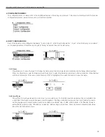
5. In the PC App, under the Settings tab
on the top toolbar, set the “AmpConnection” to be “USB”, and set “ConnectAction” to
“GetMixerState”.
6. Power ON the PLA DL210NET. When the amplifier is done starting up, the VU meters will show on the LCD Display.
7. Click on the amplifier symbol on the top left corner. It should turn green, indicating the computer is now connected to the amplifier.
The sliders and VU meters on the PC App should move when the amplifier connects to the computer, indicating that the computer
has pulled the current state information from the amplifier.
8. In the PC App, choose the Loop Mode: Dual-Loop, Phased Array, or Speaker (lower right corner above the Output VU Meters.
Note that for a single loop, “Dual-Loop” mode should be selected.
9. Connect Loop A and Loop B to corresponding outputs on the back of the PLA DL210NET. If using a single loop, connect it to
Loop A. If using a Phased Array, connect the Master loop to Loop A and the Slave loop to Loop B. If using a speaker, connect it to
the Loop A Output and the loop wire to Loop B.
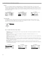
10. Run a loop test to make sure the amplifier sees the loop(s) correctly and that there are no breaks in the loop wire(s). The loop test is
the
symbol on the top toolbar. Loop test results show up in the status area just below the Output VU Meters (bottom right).
11. Calibrate the loop amplifier to the loop(s). To do this, open the calibrate window
(toolbar). If using a speaker, skip to step 15.
12. Start with Loop A. Make sure the frequency is set to 1kHz. With a field strength meter set appropriately, measure the field strength
in the center of the loop at about waist height. Adjust the Volume in the calibrate window until the field strength meter shows 0dB
(reference level). This should be 400mA/m.
13. If calibrating Dual Loops, repeat step 12 for Loop B.
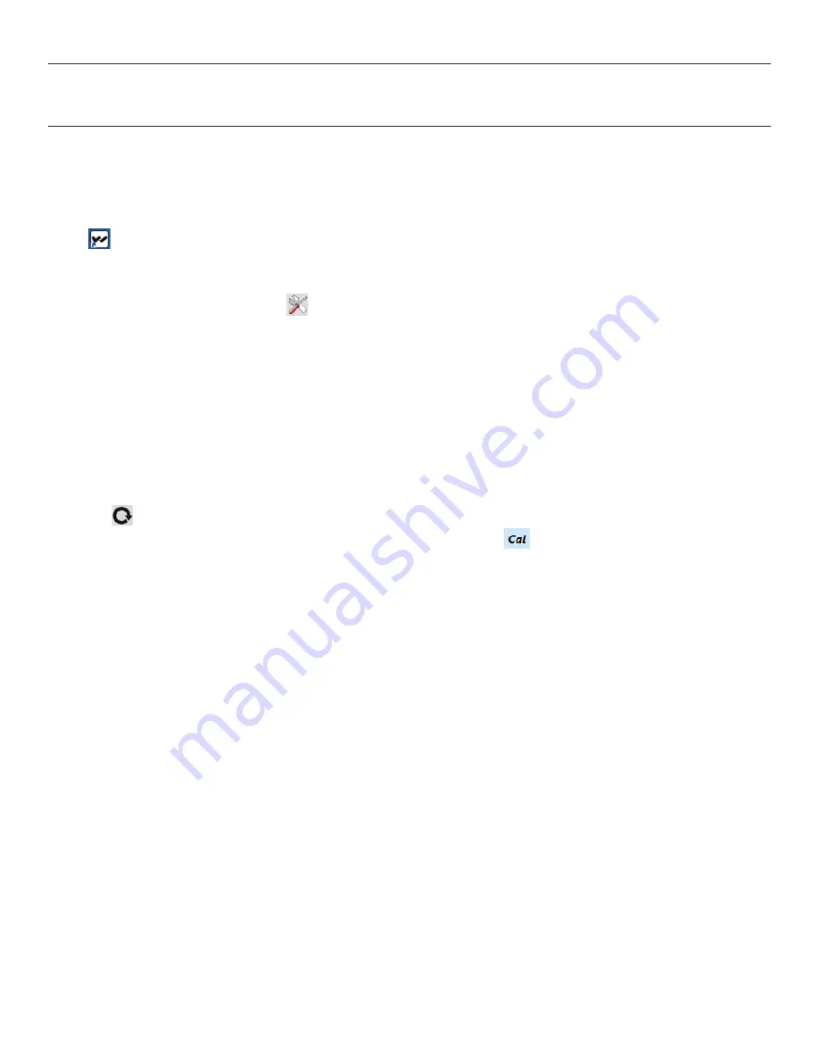
14. If calibrating a Phased-Array,
observe the “Average Current”
level
in the calibrate window for Loop A. Click on the Loop A
button to switch to Loop B in the Calibrate Window, and turn the offset up until the
average current for Loop B matches what
you observed for Loop A
. Click on the Loop B button to observe the current for both loops-they should be close. Go to step 16.
15. If calibrating a loop in “speaker” mode, Loop B is the only output that can be calibrated. Make sure the frequency is set to 1kHz.
With a field strength meter set appropriately, measure the field strength in the center of the loop at about waist height. Adjust the
Volume in the calibrate window until the field strength meter shows 0dB (reference level) for Loop B. This should be 400mA/m.
16. Best Practice Step A: Equalize the other frequencies as best you can to meet the level you have at 1kHz. To do this, run each test
frequency one at a time from the calibrate window beginning with 500Hz. Do not adjust the volume. With the Field Strength meter,
measure the field strength at each test frequency, and observe how many dB the signal strength is from 0dB. Write them down.
17. Best Practice Step B: Open the Output Effects Window for the Loop Output being used. For the test frequencies in step 16, adjust
the Bass, Midrange, Treble or Metal Compensation by the values you wrote down in step 16 to compensate for low or high points in
the frequency response. The goal is to get the frequency response ±3dB from 0dB (1kHz reference), from 100 Hz to 5kHz to meet
the IEC 60118-4 Specification.
18. In the Output Effects Window: If the loop will be used for speech, choose the “Voice” preset for the Automatic Gain Control. If a
source like music will be used, choose the “Music” preset. The Voice preset is designed for pauses in the audio, while the Music
preset is designed for more continuous audio sources. If more fine-tuning of the AGC is needed, the Custom Preset can be used to
obtain access to the Hold Time, Attack, and Release adjustments.
19. Configure the input types; i.e. condenser vs electret mic, using the Trim and Line buttons. When this has been done, power OFF
the amplifier, connect the microphones and other inputs, and power the amplifier back ON.
20. Reconnect the computer/amplifier by clicking on the amplifier symbol (top left). Now use the PC App to adjust the inputs as you
would a normal mixer. When set correctly, the overall output (bottom right VU meters) should pulse to around 0dB on average.
21. Once all of these adjustments have been finalized, use a loop receiver such as the Williams Sound PLR BP1 or PLR SR1 to listen
to the loop(s). After this test is successful, have someone with a T-Coil equipped hearing-aid (or T-Coil equipped cochlear implant)
also listen to the loop(s). The audio should be clear and intelligible.


