


3
WILDEN PUMP & ENGINEERING, LLC
WIL-11114-E-02
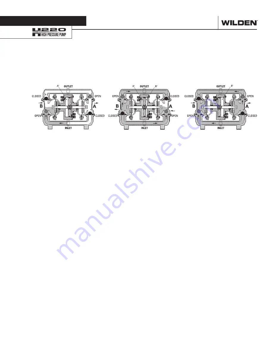
Figure 1 When air pressure is supplied to
the pump, the air valve directs pressure
to the back side of diaphragm (A) . The
compressed air moves the diaphragm
away from the center section of the
pump . Simultaneously, compressed air
is also supplied to the back side of the
power piston (A2); pressure on Area A2
exerts force on the shaft communicated
to diaphragm A . This force, when added to
the force of pressure A is connected to the
process fluid, thus providing the increase
of liquid output pressure .
During this operation the opposite
diaphragm (diaphragm B) is pulled in by
a shaft connected to the power piston (A2)
and pressurized diaphragm (A) . Diaphragm
(B) is now on its suction stroke; air behind
diaphragm (B) and piston (B2) is being
forced out to atmosphere through the
exhaust port . The movement of diaphragm
(B) towards the center section of the pump
creates a vacuum within chamber (B) .
Atmospheric pressure forces fluid into the
inlet manifold forcing the inlet valve ball
off its seat . Liquid is free to move past the
inlet valve ball and fill the liquid chamber
(see shaded area) .
Figure 2 Once the power piston reaches
the end of its stroke, the pressure relief
valve opens . This causes the air valve to
shift . This action redirects pressurized air
to the back side (air side) of diaphragm (B)
as well as the back side of the power piston
(B2) . This pressurized air forces diaphragm
(B) away from the center section while
also pulling diaphragm (A) towards the
center section . Diaphragm (B) is now on
its discharge stroke . Diaphragm (B) forces
the inlet valve ball onto its seat due to the
hydraulic forces developed in the liquid
chamber and manifold . The same hydraulic
force unseats the discharge valve ball off
of its seat and forces fluid to flow through
the pump discharge .
The pressure on the diaphragm (B) creates
a force that is combined with the force of
pressure applied to the power piston (B2) .
This total load is transferred to the liquid
creating a liquid pressure that is 3 times
the supplied air pressure .
Figure 3 At the completion of the stroke,
once again the pressure relief valve opens
and shifts the air valve . The air valve
redirects air to the back side of diaphragm
(A) and the power piston (A2), the air
behind diaphragm (B) and the power
piston (B2) is now exhausted . As the
pump reaches its original starting position,
each diaphragm has gone through one
suction and one discharge stroke of the
wetted path and one pressure and exhaust
stroke of the air distribution system . This
completes one cycle of the high pressure
H220 . NOTE: The pump may take several
cycles to completely prime depending on
the condition of the application .
S e c t i o n 3
H O W I T W O R K S — P U M P
The Wilden diaphragm pump is an air-operated, positive displacement, self-priming pump. These drawings show flow pattern
through the pump upon its initial stroke. It is assumed the pump has no fluid in it prior to its initial stroke.
Preface: The H220 uses an integral power amplifier piston together with two diaphragms to yield a pressure ratio of 3:1 [e .g ., 6 .9 bar
(100 psig) air inlet will develop liquid discharge pressures up to 20 .7 bar (300 psig)] . In the H220, air is simultaneously directed behind
the amplifier piston a well as one of the diaphragms via specialized air manifold porting . The sum of the two surface areas is three times
that of the diaphragm alone . Therefore, the discharge is amplified by a 3:1 pressure output ratio .
Summary of Contents for H200 Advanced Metal Series
Page 17: ...N O T E S...