User Manual 5.32 (2018-05) 21
Subject to change
Series EK92
EK90 smoke control dampers
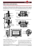
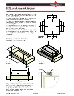
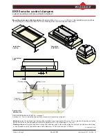
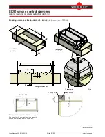
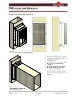
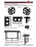
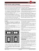
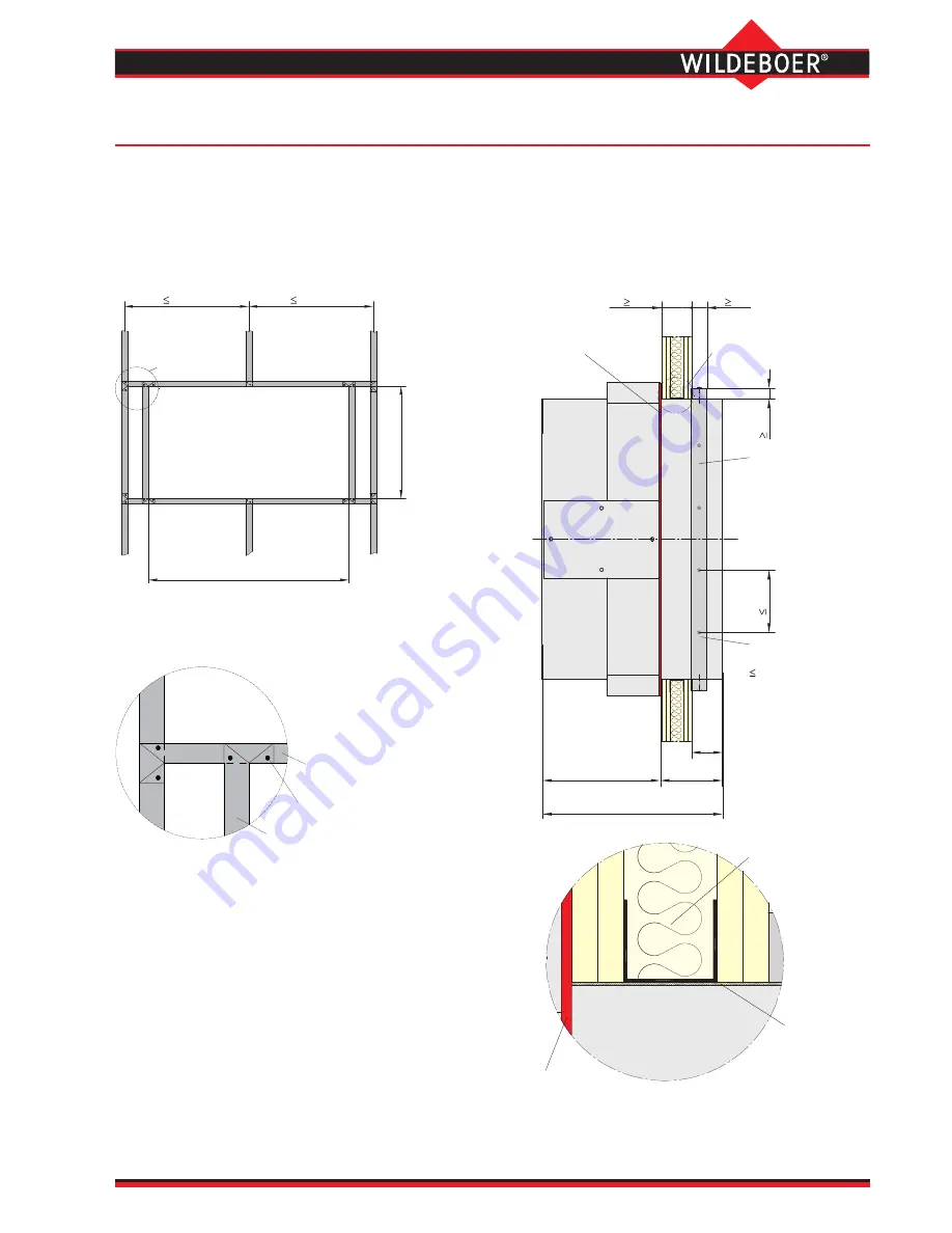
Installation in flexible walls (1) Metal stud walls, including fire walls
Installation
in
flexible walls in the form of metal stud walls with cladding on both sides and a thickness from
95 mm and stud spacing up to 1000 mm
is performed as dry installation.
EK90 smoke control dampers are used in circumferential frames made from wall profiles, in accordance with the
thickness of the wall. The frames must be connected and fixed to the studding.
Installation can be performed in a horizontal or vertical axis position.
⇒
see page 33
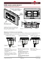
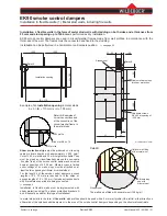
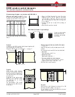
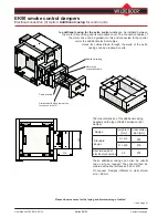
Detail B:
Shear protection strips
must be produced on site using
calcium silicate boards with approximately ≥ 500 kg/m³.
Cuts of ≥ 50 mm width and 35 mm height are suitable. They
must be glued on circumferentially around the non-opera
-
tion side (rear) of the smoke control damper and screwed
down at spacings of ≤ 200 mm. Where access is limited
under ceilings or on walls, strips must be attached on at
least the two opposing horizontal or vertical sides!
For the length L of the smoke control dampers, excess
lengths of Z ≥ 70 mm are required to fit the strips, or
excess lengths of Z ≥ 100 mm if smoke extraction ducts
with fire resistance period are being connected.
⇒
see page 4
Installation in flexible walls must be implemented with
shear protection strips! The shear protection brackets A
and B cannot be used for this type of installation!
Detail A: Examples of
corner connections and
of the connection of the
circumferential frame to
the metal studs.
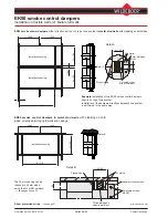
Example of an
installation opening
in metal studs
b x h = (B + 110 mm) x (H + 105 mm)
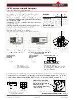
The wall can be filled with mineral wool
≤
100 kg/m³.
In metal stud walls in the form of
fire walls
, stud profiles should be used with a 2 mm wall profile (UA profile), either directly on
either side of the smoke control dampers or in the area of the smoke control dampers, depending on the structural constraints.
All dimensions in mm
CW profile
Blind rivet Ø4.8 x 7.5
UW profile
Installation opening
1000
1000
50
1
+
H
B + 110
Detail A
Chipboard screws
Ø4 x 60 at spacing of
200 mm
Stopper seal
Calcium silicate strips
for shear protection
200
35
50
W 95
L1
L2
L
Detail B
Z
Optional wall filling
with mineral wool
Stopper seal
Fill remaining
gap with
mineral wool

