


9
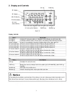
4. Wiring
Warning
Turn the power supply to the instrument off before wiring or checking. Working on or touching the terminal with
the power switched on may result in severe injury or death due to electrical shock.
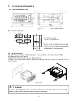
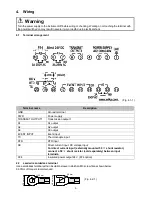
4.1
Terminal arrangement
(Fig. 4.1-1)
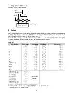
4.2
Lead wire solderless terminal
Use a solderless terminal with an insulation sleeve in which an M3 screw fits as shown below.
0.63 Nm of torque is recommended.
Terminal name
Description
GND
Ground terminal
PWR
Power supply
TRANSMIT OUTPUT1
Transmission output 1
A1
A1 output
A2
A2 output
A3
A3 output
EVENT INPUT
Event input
TC
Thermocouple input
RTD
RTD input
DC
Direct current input, DC voltage input
For direct current input (externally mounted 50
shunt resistor),
connect a 50 shunt resistor (sold separately) between input
terminals.
P24
Insulated power output 24 V (P24 option)
5
.8
m
m
m
a
x
3.2 mm
φ
3.2 mm
5
.8
m
m
m
a
x
(Fig. 4.2-1)


