Wieland Electric GmbH
Brennerstraße 10-14
96052 Bamberg
Tel.: +49 (951) 9324-0
Fax: +49 (951) 9324-198
Internet: www.wieland-electric.com
Email: [email protected]
gesis
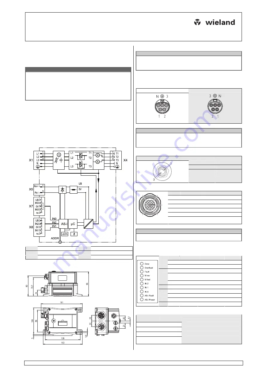
MSS PAV 3I/W 1,5
83.235.0009.5
AS-i Motor soft starter
©2010 Wieland Electric GmbH
Doc. #
BA000687
- 11/2010 (Rev. B)
A)
Important information – please read carefully
This instruction leaflet describes the assembly and connection of the gesis MSS
PAV 3I/W 1,5. Make sure to heed the warnings and adhere to the instructions. Für
commissioning, operation and maintenance please refer to following dokuments:
Operating manual gesis MSS PAV 3I/W 1,5
Doc.-Nr. BA000666
W A R NI NG
•
Electric installations, placing devices into operation and maintenance tasks may
only be carried out by qualified electricians with relevant training in accident
prevention and while adhering to applicable regulations.
•
Protective measures and mechanisms must correspond
•
to applicable regulations.
•
Damaged products may neither be installed nor operated.
•
The plug connectors may never be connected or removed under load.
•
Before opening the device, it must be removed from the mains and the load.
B)
Function description
The tree-phase electronic motor starter gesis MSS PAV 3I/W1,5 can be operated
either as direct or as reversing starter with loads up to 1.5 kW. By means of phase
angle control, gesis MSS reduces the switch-on voltage and subsequently increases
it to mains voltage. The starting current is monitored, thus it can be observed
whether the motor is running at nominal speed. In this case, relay contacts bridge
the semiconductor switches to reduce power dissipation. gesis MSS switches three-
phase motor loads and monitors the motor current. gesis MSS is an AS-i slave
which takes its supply voltage directly from the AS-i bus. The device includes an
electronic motor protection which can be parameterized via the AS-i bus. Up to
three sensors with M12 connectors can be connected.
C)
Block diagram
ADDR
Addressing jack
X5
M12, A-coded
X1, X4
RST20i5, black
X7, X8
M12, A-coded
UB
Sensor Supply 20 ... 30VDC
nc
not connected
D)
Dimensions (specifications in mm)
E)
Assembly
N O T E
•
The base must be even and capable of supporting the weight.
•
For the mounting to the base, only the provided boreholes in the base plate of
the device may be used. Additional boreholes in other locations are not permis-
sible!
Screw the device to the supporting plate with two fastening screws M4. Use
washers.
F)
Connection configuration
Three-phase connections
Input X1 (plug, black)
Motor output X4 (jack, black)
N O T E
•
L1 is bridged to T1 and not switched.
•
Phases L2 and L3 are switched by relays/TRIACS as follows:
−
clockwise sense of rotation:
L2 to T2 and L3 to T3
−
counterclockwise sense of rotation:
L2 to T3 and L3 to T2
AS-Interface
connection X5
Plug X5
Connection
Meaning
1
AS-Interface
+
3
AS-Interface
−
Digital inputs X7, X8 (M12)
Pin
Description X7/X8 Note
1
UB
24V sensor supply
1
2 IN0/IN2
digital
input
3
0V
0V sensor supply
1
4 IN0/IN1
digital
input
5
not assigned
not assigned
1
2
3
4
5
1
The supply UB for the digital inputs on X7 and X8 is
handled by the AS-Interface
N O T E
To be able to ensure compliance with protection type IP 65 all connections not
being used must be fitted with protective caps!
G)
Display elements
The status LEDs inform you about the actual state of the motor starter. See also
chapter 8 („Operation“) of the operating manual.
Nr.
Color
Name
Note
I/O bit
1 red Error
2 yellow
Overload
3 yellow
Fault
4 yellow
M
rev
Motor
counterclockwise
5
yellow
M fwd
Motor clockwise
6 yellow
IN2
Input
IN2
7 yellow
IN1
Input
IN1
8 yellow
IN0
Input
IN0
9 red AS-i
Fault
10
green
AS-i Power
AS-i voltage ok.
The operating condition of the AS-Interface is indicated as follows:
LED „AS-i
power“ (green)
LED „AS-i
fault“ (red)
Meaning
no supply voltage
normal operation
no data exchange (e.g. slave address 0)
•
periphery fault (e.g. AS-i supply overload on
initiator inputs)
=
off;
=
on;
•
=
flashing (frequency 2
Hz)


