background image

13

PLUG REPLACEMENT (ONLY FOR REWIRABLE PLUG OF UK & 

IRELAND)

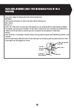
If you need to replace the fitted plug then follow the instructions below.

IMPORTANT

The wires in the mains lead are colored in accordance with the following code:

Blue = Neutral

Brown = Live

As the colors of the wires in the mains lead of this appliance may not correspond with the colored markings identifying 

the terminals in your plug, proceed as follows. The wire which is colored blue must be connected to the terminal which is 

marked with N. The wire which is colored brown must be connected to the terminal which is marked with L.

Warning!

Never connect live or neutral wires to the earth terminal of the plug. Only fit an approved 13A BS1363/A plug and the correct 

rated fuse.

Note: If a moulded plug is fitted and has to be removed take great care in disposing of the plug and severed cable, it must 

be destroyed to prevent engaging into a socket.


13 Amp fuse approved

to BS1362

Connect

Blue to N

(neutral)

Outer sleeve

firmly clamped

Brown L(live)

Cable grip

Summary of Contents for 223740

Page 1: ...PBS900G 1 223740 BELT SANDER 920W 76x533MM...

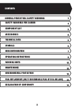
Page 2: ...2 12 12 13 14 COMPONENT LIST SAFETY WARNINGS FOR SANDER ACCESSORIES TECHNICAL DATA SYMBOLS NOISE INFORMATION OPERATING INSTRUCTIONS MAINTENANCE WORKING HINTS ENVIRONMENTAL PROTECTION PLUG REPLACEMENT...

Page 3: ...AFETY a Stay alert watch what you are doing and use common sense when operating a power tool Do not use a power tool while you are tired or under the influence of drugs alcohol or medication A moment...

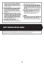
Page 4: ...th sharp cutting edges are less likely to bind and are easier to control g Use the power tool accessories and tool bits etc in accordance with these instructions taking into account the working condit...

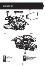
Page 5: ...ENT LIST Front handle Dust exhaust outlet Lock on button On Off switch Rear handle Dust bag Belt tracking adjustment knob Variable speed control Belt tension release lever 1 3 2 4 7 6 5 8 9 1 2 3 4 5...

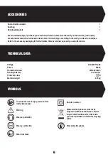
Page 6: ...personnel can assist you and offer advice SYMBOLS TECHNICAL DATA To reduce the risk of injury read all of this instruction manual Warning Wear ear protection Wear eye protection Wear dust mask Double...

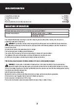
Page 7: ...ol and ensuring it is sharp and in good condition The tightness of the grip on the handles and if any anti vibration accessories are used And the tool is being used as intended by its design and these...

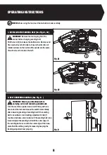
Page 8: ...belt centering adjustment Turn the machine upside down hold it firmly with one hand start the tool and release the switch immediately after observing tracking of sanding belt If the sanding belt runs...

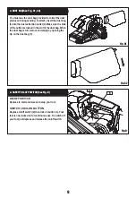
Page 9: ...t bag When the dust bag is full remove and empty by opening the zip on the dust bag 5 ON OFF SWITCH Depress to start and release to stop your tool SWITCH LOCK ON BUTTON Depress on off switch 4 then lo...

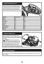
Page 10: ...t the variable speed control dial 8 to increase or decrease the speed according to the material and sanding belt specification to be used also possible during no load operation See the table below for...

Page 11: ...as shown Carefully cut the drive belt if not already broken and remove from your belt sander Fit your new drive belt around the large pulley Then install onto the small pulley by rotating clockwise an...

Page 12: ...lection WORKING HINTS FOR YOUR BELT SANDER Remove the plug from the socket before carrying out any adjustment servicing or maintenance Your power tool requires no additional lubrication or maintenance...

Page 13: ...ollows The wire which is colored blue must be connected to the terminal which is marked with N The wire which is colored brown must be connected to the terminal which is marked with L Warning Never co...

Page 14: ...achinery Directive 2014 30 EU Electromagnetic Compatibility Directive 2011 65 EU EU 2015 863 RoHS Restriction of Hazardous Substances Directive and conforms to the following standards Standards specif...

Page 15: ......

Page 16: ...Customer Helpline 0345 2005409...

Reviews: