background image

Weldmatic 270C

Model No CP136-2, Iss A 08/12   

11

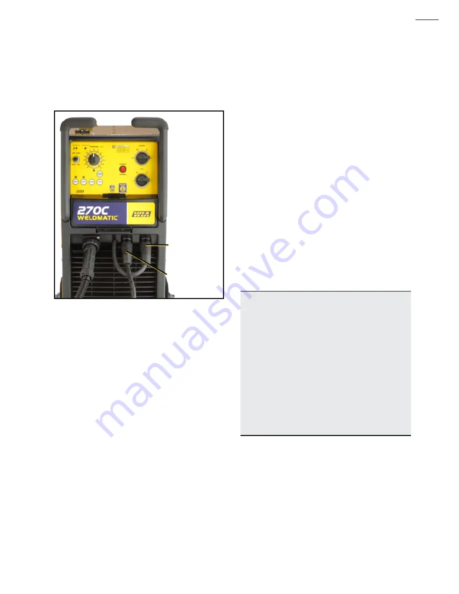
on the Power Source, and the ‘WELDING’ 
lead from the wirefeeder into the (-) socket 
on the Power Source, as in Figure 4.

Fig 4 

Negative Wire

To wirefeeder

To work clamp

Fitting the gas cylinder

Place the gas cylinder on the tray at the rear 
of the welder. Retain the cylinder with the 
chain provided.

Fit the gas regulator to the cylinder. DO NOT 

apply grease or oil to these joints.

Fit the end of the supplied gas hose to the 
gas larb at the rear of the machine. Secure 
with clamp. Fit other end to nut and tail 
already attached to regulator and secure 
with clamp.

Wirefeeder

The 4RD wirefeeder is supplied fitted with 
WF027 bottom rollers which are suitable for 
both 0.9 mm and 1.2 mm diameter steel wire.

Fitting The Gun and Cable Assembly

The supplied welding gun/cable assembly is 
equipped with a ‘Euro’ wirefeeder connector 
which incorporates all required connection 
points for welding current, shielding gas and 
gun switch control.

To attach the gun/cable assembly to 
the wirefeeder mechanism, engage the 
mating parts of the male and female Euro 
connectors, then rotate the locking ring 
clockwise to firmly secure the connection.

Fitting the Consumable Wire

The quality of the consumable 
wire greatly affects how reliably a 
gas metal arc welder will operate. 
For best results when welding 
mild steel, we recommend quality 
WIA AUSTMIG ES6. Dirty, rusty or 
kinked wire will not feed smoothly 
through the gun cable and will 
cause erratic welding. Deposits 
from the wire will clog the gun 
cable liner requiring it to be 
replaced prematurely.

Place the spool of welding wire onto the 
spool holder. The location pin should mate 
with a hole provided on the wire spool body. 
Secure the spool with plastic nut. Check 

the adjustment of the spool brake, which 

should be set to prevent over run of the wire 
spool at the end of a weld, without unduly 
loading the wirefeed motor. The braking can 

be adjusted by using an 8 mm allen key to 
adjust Hex head bolt inside the hub.

Summary of Contents for WELDMATIC 270C

Page 1: ...CP136 40 Rev B Weldmatic 270C compact internal wirefeeder Operators Manual Weldmatic 270C MIG welder Model No CP136 2 Iss A 0812...

Page 2: ...Welding Industries of Australia An ITW Company Telephone 1300 300 884 Facsimile 1300 301 884 Email Info welding com au www welding com au...

Page 3: ...fe Practices 2 1 Introduction 5 2 Receiving 5 3 Specifications 6 4 Controls 7 5 Installation 9 6 Normal Welding Sequence 12 7 Basic Welding Information 13 8 General Maintenance 14 9 External Trouble S...

Page 4: ...Filter Lens Amps TIG MMAW MIG Pulsed MIG 0 100 10 9 10 12 13 100 150 11 10 10 12 13 150 200 12 10 11 11 12 12 13 200 300 13 11 12 13 12 13 300 400 14 12 13 14 400 500 13 14 14 500 14 14 Read first Th...

Page 5: ...unless coating is removed from the work surface the area is well ventilated or the operator wears an air supplied respirator Work in a confined space only while it is being ventilated and if necessar...

Page 6: ...nitrogen or carbon dioxide and using protective equipment as recommended in AS 1674 2 Water filling just below working level may substitute for inerting Hollow castings or containers must be vented b...

Page 7: ...m to 1 2mm diameter The smaller wire sizes are used when welding at lower currents such as sheet metal applications Increasing the wire diameter permits higher welding currents to be selected A common...

Page 8: ...urrent 30 270 Amps Open Circuit Voltage 17 41 V Shipping weight 127 kg Power source weight 85 kg Mains Circuit Breaker Rating 25 Amps Supply plug 15 Amp 240 V for initial commissioning only Fitted Sup...

Page 9: ...o not switch the equipment off as the cooling fan will assist the resetting of the thermostats 4 Controls 3 Arc start This control can be set to modify arc starting conditions For many applications th...

Page 10: ...owed by rapid acceleration so that the arc does not flare up and damage the tip Even if an arc is not established within one second of the gun switch being operated the wire feed accelerates to select...

Page 11: ...fitted with a 3 metre 3 core 2 5 mm2 Heavy Duty PVC mains power supply cable with moulded 3 pin 15 Amp Single Phase plug 15 Amp Supply Limited Output To operate the machine with the 15 Amp plug from...

Page 12: ...Successful Operation Successful operation will depend on a number of factors Variation in circuit breaker thresholds Ambient temperature Number of previous circuit breaker operations Actual weld condi...

Page 13: ...d connection points for welding current shielding gas and gun switch control To attach the gun cable assembly to the wirefeeder mechanism engage the mating parts of the male and female Euro connectors...

Page 14: ...he gas valve is de energised and the flow of shielding gas ceases Compression screw Top roller arms Fig 5 WF042 Four Roll Drive Inlet guide Drive rollers Feeding the Consumable Wire At the wirefeeder...

Page 15: ...excess build up of spatter When welding aluminium particular care must be taken with all aspects of shielding gas delivery and workpiece preparation in order to avoid weld porosity Establishing a Wel...

Page 16: ...ze and type for the wire in use Check also that the drive groove is aligned with the wire and that the groove is not worn 2 Gun cable liner is clear of dust and swarf build up When replacement becomes...

Page 17: ...identify the fault condition the equipment should be returned to a WIA Service agent Phone 1300 300 884 for details of your nearest service agent Power source has no output and no wirefeed when gun s...

Page 18: ...s required 5 Check the work piece surface and MIG wire for contamination Water oil grease or paint can result in porosity in the weld the equipment off as the cooling fan will assist the resetting of...

Page 19: ...Weldmatic 270C Model No CP136 2 Iss A 08 12 17 10 Circuit Diagram Power Source Fig 9 Power Source Circuit Diagram...

Page 20: ...Reliability Performance 11 1 Assembly and Parts List Weldmatic 270C Power Source Fig 10 Weldmatic 270C Power Source Assembly 9 8 14 12 16 18 5 6 7 3 2 1 17 15 23 19 21 22 28 33 34 30 32 29 27 26 25 2...

Page 21: ...0304 Plastic Front 1 20 L0022 Control Transformer 1 21 E0058 Contactor 1 22 E0041 Gas Valve 24 vdc 1 23 PWA010N Fan On Demand PCB 1 24 FAN008 Fan Assembly 1 25 TFM061 Welding Transformer Assembly Wire...

Page 22: ...WF026 0 6 0 8 mm Solid Wire 2 WF028 1 2 1 6 mm Solid Wire 2 WF029 1 0 1 2 mm Aluminium 2 WF030 1 0 1 2 mm Flux Cored Wire 2 WF031 1 2 1 6 mm Flux Cored Wire 2 3 WF037 Pressure screw complete 1 4 W26...

Page 23: ...ips page 24 Contact Tip 3 BE4335 Gas Diffuser Head 4 BE4323 Cap 5 BEQT2 45 BEQT2 30 Body Tube 2 45o Body Tube 2 30o 6 GUN002 Handle Kit includes both halves screws trigger 7 GUN003 Trigger 8 GUN005 Ri...

Page 24: ...un end compress the liner within the gun cable then cut it 20 mm past the end of the body tube 5 Refit head tip and nozzle Fig 13 Replacing the gun cable liner Wire diameter Short series 25mm 0 6 mm B...

Page 25: ...ded in the original purchase package The obligation of Welding Industries of Australia under this warranty is limited to the circumstances set out above and is subject to The customer being able to pr...

Page 26: ...24 Operators Manual Quality Reliability Performance Notes...

Page 27: ...Weldmatic 270C Model No CP136 2 Iss A 08 12 25 Notes...

Page 28: ......

Reviews: