background image

13

12

Establishing a Weld Setting
Once the consumable wire type, wire size 

and shielding gas have been chosen, the 

two variables that are adjusted in order to 

obtain a the desired weld setting are;
–  Wirefeed speed,
–  Welding arc voltage.
The wirefeed speed determines the 

welding current; increasing the speed 

increases the current, and decreasing it 

decreases current. 
The selected wirefeed speed must be 

matched with sufficient arc voltage; a speed  

increase requires an increase of arc voltage.
If the voltage is too low the wire will stub 

and stutter, and there will not be a steady 

arc. If the voltage is too high the arc will 

be long with  metal transfer occurring as a 

series of large droplets. 
Important: Do not operate the Voltage 

Control switches during welding.
The weld setting should be chosen to suit 

the application and the thickness of the 

metal to be welded. It is important to check 

that the deposited weld provides sufficient 

strength to suit the application. 
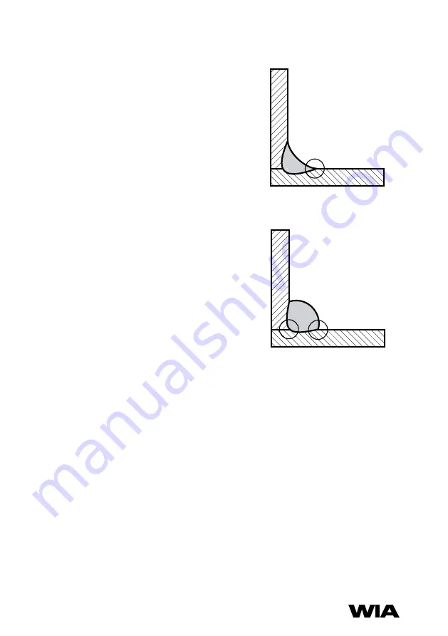
A “good” weld will have the characteristics 

illustrated in Figure 4. The weld has penetrated 

into the parent metal, fusing the root of the 

joint where the two plates meet, and the 

weld blends smoothly into the side walls.
A “bad” weld is shown in Figure 5. The weld 

has not penetrated the joint root, and there 

is poor side wall fusion. This lack of fusion 

would normally be corrected by increasing 

the arc voltage, or by increasing both 

wirefeed speed and arc voltage to achieve 

a higher current weld setting.

Fig 5 “Bad” Weld

Fig 4 “Good” Weld

Summary of Contents for CP146-1

Page 1: ...MIG Welder WELDING COM AU OPERATORS MANUAL CP146 1 From serial numbers CP1462A...

Page 2: ...f ITW Australia Pty Ltd ABN 63 004 235 063 1300 300 884 Email info welding com au welding com au WELDWELL NEW ZEALAND A Division of ITW New Zealand NZBN 9 429 039 833 129 GST NO 080177186 0800 9353 93...

Page 3: ...llation 10 6 Normal Welding Sequence 12 7 Basic Welding Information 12 8 General Maintenance 14 9 External Trouble Shooting 15 10 Trouble Shooting Chart 16 11 Circuit Diagrams 18 12 Assembly Parts Lis...

Page 4: ...er Lens Amps TIG MMAW MIG Pulsed MIG 0 100 10 9 10 12 13 100 150 11 10 10 12 13 150 200 12 10 11 11 12 12 13 200 300 13 11 12 13 12 13 300 400 14 12 13 14 400 500 13 14 14 500 14 14 READ FIRST The inf...

Page 5: ...h or containing materials that emit fumes should not be heated unless coating is removed from the work surface the area is well ventilated or the operator wears an air supplied respirator Work in a co...

Page 6: ...ing depending on the combustible s solubility followed by purging and inerting with nitrogen or carbon dioxide and using protective equipment as recommended in AS 1674 2 Water filling just below worki...

Page 7: ...e used when welding at lower currents such as sheet metal applications Increasing the wire diameter permits higher welding currents to be selected A common application of G M A W is for welding Mild S...

Page 8: ...Amp 27 5 V 20 duty 150 Amp 21 5 V 60 duty 120 Amp 20 V 100 duty Welding Current 30 270 Amps Open Circuit Voltage 17 41 V Shipping weight 115 kg Power source only 142 kg Includes wirefeeder leads Main...

Page 9: ...rate Switch 4 Coarse Voltage Control This switch provides Coarse adjustment of the output welding voltage over four ranges 4 POWER SOURCE CONTROLS 5 Fine Voltage Control This switch provides Fine adju...

Page 10: ...greater The minimum recommended supply circuit breaker rating for a Weldmatic 270 is 25 Amps For Australian and New Zealand installation a 32 Amp plug is the closest suitable size The supply circuit...

Page 11: ...osite cable interconnecting lead Check all connections are firmly made to ensure good electrical contact and to prevent gas leaks Output Voltage Polarity The design of the Weldmatic 270 allows selecti...

Page 12: ...y the consumable wire to be used Many proprietary shielding gas mixtures are available The recommended shielding gases for use with the Weldmatic 270 are Mild Steel Argon 5 to 25 Carbon Dioxide 100 CO...

Page 13: ...occurring as a series of large droplets Important Do not operate the Voltage Control switches during welding The weld setting should be chosen to suit the application and the thickness of the metal to...

Page 14: ...removed by the use of a dry low pressure compressed air or a vacuum cleaner The machine should be blown out with compressed air at least every 12 months as grinding dust can settle on PCB componentry...

Page 15: ...uipment should be returned to a WIA Service agent Phone 1300 300 884 for details of your nearest service agent If you are in New Zealand and the following checks do not identify the fault condition th...

Page 16: ...he fan running until the machine has cooled sufficiently The duty cycle should be observed and understood No welding current but display on The connections may not be made securely Ensure all connecti...

Page 17: ...atch mode should be switched off Weld is contaminated with small bubbles presence of porosity Air in the gas hose The torch gas hose has not been purged sufficiently The gas hose is not securely conne...

Page 18: ...Weldmatic 270 Operator Manual Model No CP146 2 18 11 CIRCUIT DIAGRAMS POWER SOURCE Fig 7 Power Source Circuit Diagram...

Page 19: ...19 12 ASSEMBLY AND PARTS LIST WELDMATIC 270 POWER SOURCE Fig 8 Weldmatic 270 Power Source Assembly 18 20 22 26 24 25 23 19 15 13 12 6 4 16 11 17 14 5 7 8 3 2 1 9 10 21...

Page 20: ...4 Position 1 12 E0054 Switch Fine 4 Position 1 13 TC265 5 8 UNF Nipple 1 14 TC266 5 8 UNF Nut 1 15 CX58 Socket Dinse 2 16 E0024 Circuit Breaker 5 Amp 1 17 MR230304 Plastic Front 1 18 PWA010 Fan On Dem...

Page 21: ...act Tip 3 BE4335 Gas Diffuser Head 4 BE4323 Cap 5 BEQT2 45 BEQT2 30 Body Tube 2 45 supplied Body Tube 2 30 6 GUN002 Handle Kit includes both halves screws trigger 7 GUN003 Trigger 8 GUN005 Rigid Casin...

Page 22: ...0mm BE7496 1 2mm BE7490 Tips To replace liner Disconnect gun cable assembly at the Euro adaptor Remove nozzle 1 and head 3 Withdraw old liner from the wirefeeder end Insert new liner and refit gun cab...

Page 23: ...our products may result in the loss of any user generated data Please ensure that you have made a copy of any data saved on your product Any handling and transportation costs and other expenses incurr...

Page 24: ...e goods repaired or replaced if the goods fail to be of acceptable quality and the failure does not amount to a major failure The benefits given by this warranty are in addition to other rights and re...

Page 25: ...ian warranty conditions the customer should return the Product to the original place of purchase with proof of purchase or contact Weldwell on 0800 9353 9355 The warranty shall not apply to parts that...

Page 26: ...Weldmatic 270 Operator Manual Model No CP146 2 26 NOTES...

Page 27: ...27 NOTES...

Page 28: ...A Division of ITW Australia Pty Ltd ABN 63 004 235 063 1300 300 884 Email info welding com au welding com au WELDWELL NEW ZEALAND A Division of ITW New Zealand NZBN 9 429 039 833 129 GST NO 080 177 18...

Reviews: