
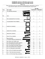


3525DUETa Addison 37"W Storage Console
3526DUETa Addison 54"W Storage Console
Assembly Instructions
3525DUETa_3526DUETa
— Page 6 — 08/18
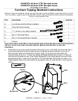
5.
To move the Adjustable Shelves (C and D), remove the #6 x 1/2" Undercut Screws (N) and the
Shelves (C and D). Reposition the Shelf Brackets (ZE) to the desired positions, replace the
shelves and insert the screws. See Figures 5 and 5a.
Continued on Page 7
Fig. 5
N
ZE
Fig. 5a
D
Doors removed for illustration purposes.
C


