background image

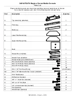
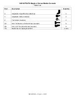
3461AFCAFb Stayton Corner Media Console 

Assembly Instructions


3461AFCAFb 

— Page 8 — 04/14 

 
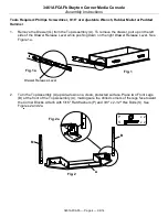
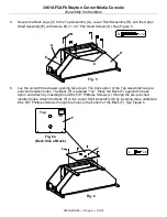
10.  Position the unit at the desired location. Locate a stud in the wall behind each side of the unit.   

A strong small magnet is helpful to locate the studs in the wall. The magnet will help you find the 
nails or screws used to attach the wall to the studs. When you have found a screw you have 
found a stud. Studs are usually 16" on center.  Attach a Clip (T1) to each wall stud with #8 x 2" 
Black Screws (T3). See Figure 10a.  
 
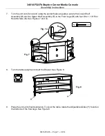
The clips attached to the furniture will attach to the underside of the top adjacent to each wall 
clip.  Attach the second clip from each kit to the unit with #6 x 5/8" Philtruss Screws (T5). See 
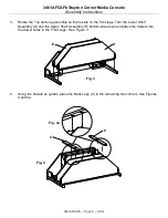
Figure 10b. Connect the two clips with the Nylon Zip-Tie (T2). 

Pull the Nylon Zip-Tie (T2) tight 

so there is no slack

. See Figures 10c and 10d.  We have included an extra Nylon Zip-Tie in 

each kit; if you should need to move your furniture cut the Zip-Ties that you are using and 
replace with the extra Zip-Ties when the furniture is back in place. 
 

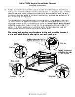
The screws attaching your furniture to the wall must be inserted 
into a wall stud. Do not attempt to use wall anchors.


Pull tight 

Wood 

Stud 


Fig. 10c 

Pull the Nylon Zip-Tie (T2) 

tight so there is no slack.  T1 

T2 

T5 

T3 

(Side view) 

Fig. 10a 

T1 

T3 

T5 

Top 

Fig. 10b 

Fig. 10d 

Wood 

Stud 


Attach the second  

restraint to this side 

and the wall. 

Summary of Contents for 3461AFCAFb

Page 1: ...ed with your piece of Whittier Wood Furniture When you receive your furniture be sure to find and properly install the tipping restraint s If you cannot locate the restraint s please contact us immediately for replacement Notice to California Customers California Prop 65 requires consumer goods to be labeled if any one of 850 different chemicals or substances including wood dust is present even in...

Page 2: ... D Lower Shelf Assembly 1 E Upper Shelf Assembly 1 F Back 1 G Drawer Box inserted 1 H Drawer Face installed 1 I Drawer Slides pre installed sets 1 J 6 x 3 4 Philtruss Screw inserted 6 K 6 x 1 2 Philtruss Screw inserted 6 L 6 x 5 8 Philtruss Screw 6 N 8 x 1 1 4 Pan Head Screw 40 24 inserted Oa 8 x 1 1 2 Machine Screw Tuscan installed 4 P 5 16 Flat Washer 2 Q 8 Washer inserted 22 R 3 8 x 1 Insert Nu...

Page 3: ...AFb Page 3 04 14 Part Description Quantity X Adjustable Angle Bracket attached 2 Y Adjustable Glide installed 2 Z Tack Glide inserted 2 ZA 8 x 7 8 Black Lo Profile Screw inserted 6 ZB 10 x 3 4 Pan Head Screw inserted 6 TR Media Zip Tie Tipping Restraint 2 sets ...

Page 4: ... the left side of the Drawer Release Lever while pushing down on the right Drawer Release Lever See Figure 1a 2 Turn the Top Assembly A upside down on a clean protected surface Place two Front Legs B at the front of the Top Assembly A making sure the drilled corners of the legs face toward the Corner Blocks Attach with 5 16 Flat Washers P and 3 8 x 2 1 2 Hex Bolts S See Figures 2 and 2a Fig 1 Draw...

Page 5: ...bly so that is sets on the front legs Turn the Lower Shelf Assembly D and the Upper Shelf Assembly E bottom side down and place the dowels into the dowel holes in the Front Legs See Figure 3 4 Using the dowels as guides place the Back Legs C in the remaining two corners See Figures 4 and 4a Fig 4 Fig 4a C C Fig 3 D E ...

Page 6: ...ening face down The back apron of the Top Assembly has pre punched location holes The Back F is labeled Top Place the Back F against the back apron and attach by inserting three 6 x 5 8 Philtruss Screws L through the pre punched location holes Attach the Back F to the Lower Shelf Assembly D by inserting three additional 6 x 5 8 Philtruss Screws through the holes in the bottom of the Back F See Fig...

Page 7: ...ower Shelf Assembly D and the Upper Shelf Assembly E to the Front Legs B with four 8 x 1 1 4 Pan Head Screws N See Figures 7 and 7a 8 Turn the table upright and insert the Drawer See Figure 8 9 Place the unit at its final destination To level the table rotate the Adjustable Glides Y found on the bottoms of the front legs See Figure 8 Fig 8 Y Y Fig 7 N x 4 Fig 7a N ...

Page 8: ... adjacent to each wall clip Attach the second clip from each kit to the unit with 6 x 5 8 Philtruss Screws T5 See Figure 10b Connect the two clips with the Nylon Zip Tie T2 Pull the Nylon Zip Tie T2 tight so there is no slack See Figures 10c and 10d We have included an extra Nylon Zip Tie in each kit if you should need to move your furniture cut the Zip Ties that you are using and replace with the...

Reviews: