background image

3460CAFb Stayton Media Console; 

3462CAFb Stayton Media Center 

Assembly Instructions
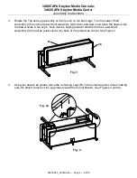


7. 

Lay the unit with the drawer opening face down. The back apron of the Top Assembly has pre-
punched location holes. Place the Back Assembly (E) with the horizontal cleat of the top edge 
against the back apron of the Top Assembly. Attach by inserting three #6 x 5/8" Philtruss 
Screws (K) through the pre-punched location holes in the Back Apron. Insert three additional #6 
x 5/8" Philtruss Screws through the holes in the bottom edge of the Back Assembly into the 
Lower Shelf Assembly. 


8. 

Turn the table upright and insert the Drawer. See Figure 8. 


9. 

Place the unit at its final destination. To level the table, rotate the Adjustable Glides (V) found on 
the bottoms of the legs. See Figure 8. 


Continued on Page 7


Fig. 8 

Fig. 7 

x 6 

(Front View of 

Back Assembly) 

Fig. 7a 

TOP 

3460CAFb_3462CAFb — Page 6 — 08/15 

Summary of Contents for 3460CAFb

Page 1: ...operly install the tipping restraint s If you cannot locate the restraint s please contact us immediately for replacement Notice to California Customers California Prop 65 requires consumer goods to b...

Page 2: ...1 H Drawer Slides pre installed sets 1 1 I 6 x 3 4 Philtruss Screw inserted 4 6 J 6 x 1 2 Philtruss Screw inserted 4 6 K 6 x 5 8 Philtruss Screw 6 6 M 8 x 1 1 4 Pan Head Screw 42 34 inserted 45 37 ins...

Page 3: ...side of the Drawer Release Lever while pushing down on the right Drawer Release Lever See Figure 1a 2 Turn the Top Assembly A upside down on a clean protected surface Place two Legs B at the back of...

Page 4: ...and place the dowels into the dowel holes in the Legs Note that the tipping restraint attached to the Lower Shelf Assembly Cb must be positioned to the back of the product as shown See Figure 3 4 Usi...

Page 5: ...rs P and 3 8 x 2 1 2 Hex Bolts R See Figures 5 and 5a 6 Turn the unit onto its top and using the pocket holes as guides secure the Lower Shelf Assembly Cb and the Upper Shelf Assembly D to the Legs B...

Page 6: ...x 5 8 Philtruss Screws K through the pre punched location holes in the Back Apron Insert three additional 6 x 5 8 Philtruss Screws through the holes in the bottom edge of the Back Assembly into the L...

Page 7: ...corner of the baseboard and floor see the instruction included inside the tipping restraint kit for an alternate installation 10 Decide where you want to place the piece of furniture in your room Mar...

Page 8: ...etween the Cam Buckle A and the back apron of the item is tight See Figures 11 and 11a If you need to move the piece of furniture reach beneath and locate the buckle which connects the two sections of...

Reviews: