Whittier Wood 1187RGBc Assembly Instructions Manual Download Page 8

1187RGBc Stonewood 10-Drawer Dresser 

Assembly Instructions


1187RGBc — Page 8 — 04/19 

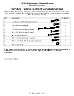
Furniture Tipping Restraint/Long Instructions 

Before you begin this assembly, identify each part and make sure the quantities received match what is on this 

list. If you need to replace a part, contact Whittier Wood Furniture customer service and refer to the following 

list for its name and letter code. 
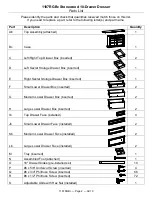
 

Part 

Description 

Quantity 

A   

Cam Buckle and Short Strap (installed) 


B   

Plastic Bracket (installed) 


C   

1" x 1350mm Long Strap (installed) 


D   

#8 x 1-5/8" Black Screw (inserted) 


E   

#8 x 3" Pan Head Screw 


F   

#10 x 1" Oval Head Screw (inserted) 


G   

#10 x 1-1/4" Black Pan Head Screw (inserted) 


H   

Washer (inserted) 


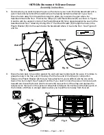
If you have a stone or tile floor or do not wish to drive screws into the corner of the baseboard 
and floor see the instruction included inside the tipping restraint kit for an alternate 
installation. 


Continued on Page 9 


Summary of Contents for 1187RGBc

Page 1: ...nt s please contact us immediately for replacement Drilling sawing sanding or machining wood products can expose you to wood dust a substance known to the state of California to cause cancer Avoid inhaling wood dust or use a dust mask or other safeguards for personal protection For more information go to www p65warnings ca gov wood This product can expose you to chemicals including formaldehyde wh...

Page 2: ...er Box inserted 1 E Right Secret Storage Drawer Box inserted 1 F Small Lower Drawer Box inserted 2 G Medium Lower Drawer Box inserted 2 H Large Lower Drawer Box inserted 2 Ib Top Drawer Face installed 4 Jb Small Lower Drawer Face installed 2 Kb Medium Lower Drawer Face installed 2 Lb Large Lower Drawer Face installed 2 M Tray inserted 1 N Assembled Foot attached 1 O 16 Drawer Slides pre installed ...

Page 3: ...installed 16 ZC Hinged Drawer Stop attached 2 ZD 5 16 x 3 4 Insert Nut inserted 1 ZE 1 4 x 20mm Insert Nut inserted 4 ZF 4 x 10mm Insert Nut inserted 8 ZG Knob attached 16 ZH Knob Plate attached 16 ZI Hex Bumper attached 4 ZJ Velvet back of sleeper 50 x 20mm attached 2 ZK Velvet Tray bottom 236 x 186mm attached 1 ZL Velvet Secret storage drawer bottom 385 x 320mm attached 2 ZM Short Velvet 200 x 1...

Page 4: ... two middle drawers To access either of these storage areas open the Small Lower Drawer F that is beneath the drawer you wish to access Reach in until you find the Hinged Drawer Stop ZC attached to the bottom left side of the Left Secret Storage Drawer D or attached to the bottom right side of the Right Secret Storage Drawer E Pull the Hinged Drawer Stop ZC forward and then pull drawer D or E out ...

Page 5: ...es ZO found at the corners of the unit and the Adjustable Glide with Hex Nut S at the bottom of the Assembled Foot N until the unit is level It is important the Assembled Foot N support the weight of the dresser The Adjustable Glide with Hex Nut S on the Assembled Foot N can be adjusted using a wrench See Figure 4 5 If you need to remove your drawers pull up on the left Drawer Release Lever while ...

Page 6: ...nti Tip Drawer Interlock System it is important that the drawer be installed back in its original location Numbers and letters are stamped on the back of the drawers Stamping sequence starts at the bottom moves to the top and designated left or right Drawer back stamping example Continued on Page 7 1L Fig 6 1R 2L 3L 4L 2R 3R 4R 4LC 4RC ...

Page 7: ...ngled toward the front of the case you cannot remove the First Drawer Move the upper arms of the Anti tip Snapper to the unlocked position as shown in Figure 7e You can then remove the First Drawer as shown in Step 5 To reinstall the drawers install the First Drawer then move the upper arm of the Anti tip Snapper to the forward locked position Now you can reinstall the Second Drawer Fig 7 Drawer C...

Page 8: ... list for its name and letter code Part Description Quantity A Cam Buckle and Short Strap installed 1 B Plastic Bracket installed 3 C 1 x 1350mm Long Strap installed 1 D 8 x 1 5 8 Black Screw inserted 2 E 8 x 3 Pan Head Screw 2 F 10 x 1 Oval Head Screw inserted 1 G 10 x 1 1 4 Black Pan Head Screw inserted 2 H Washer inserted 1 If you have a stone or tile floor or do not wish to drive screws into t...

Page 9: ...acket B into the seam below the baseboard where it meets the floor See Figures 8 and 8a 9 Move the item back into position against the wall and reach underneath the piece of furniture to grasp the loop in the free end of the strap Pull the free end of the Strap C until portion between the Plastic Bracket B that you have attached to your wall floor and the one at the back of the item is tight See F...

Reviews: