Whittier Wood 1130GACg Assembly Instructions Manual Download Page 2

1130GACg; 1130CAFg & 1131GACg; 1131CAFg McKenzie Dresser 

Parts List


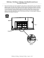
1130GACg_1130CAFg_1131GACg_1131CAFg — Page 2 — 03/17 

Please identify the parts and check that quantities received match those on this list. 

If you need to replace a part, refer to the following letter and part name. 


Part 

Description 

Quantity 

1130GACg 

1130CAFg 

1131GACg 

1131CAFg 

Top Assembly 


Bf 

Case 


Small Drawer Box (inserted) 


Medium Drawer Box (inserted) 


Large Drawer Box (inserted) 


Small Drawer Face (installed) 


Medium Drawer Face (installed) 


Large Drawer Face (installed) 


1/4" x 20mm Insert Nut (inserted) 


M4 x 10mm Insert Nut (inserted) 


Small Adjustable Glide (installed) 


Knob (attached) 


Me 

#8 x 1-1/2" Machine Screw Tuscan (installed) 


16" Drawer Slides (pre-installed sets) 


#6 x 1/2" Philtruss Screw (inserted) 


54 

60 

#6 x 3/4" Philtruss Screw (inserted) 


48 

54 

Qe 

#8 x 7/8" Black Lo-Profile Screw (inserted) 


36 

40 

#8 x 1-1/8" Lo-Profile Screw (inserted) 


#8 x 1-1/4" Pan Head Screw (inserted) 


14 

17 

#8 x 2" Black Screw (inserted) 


#8 x 1-3/8" Lo-Profile Screw (inserted) 


10 

Adjustable Glide with Hex Nut (installed) 


Summary of Contents for 1130GACg

Page 1: ...cement Drilling sawing sanding or machining wood products can expose you to wood dust a substance known to the state of California to cause cancer Avoid inhaling wood dust or use a dust mask or other safeguards for personal protection For more information go to www p65warnings ca gov wood This product can expose you to chemicals including formaldehyde which are known to the State of California to ...

Page 2: ...2 F Small Drawer Face installed 3 4 G Medium Drawer Face installed 2 2 H Large Drawer Face installed 2 2 I 1 4 x 20mm Insert Nut inserted 4 4 J M4 x 10mm Insert Nut inserted 8 8 K Small Adjustable Glide installed 4 4 L Knob attached 7 8 Me 8 x 1 1 2 Machine Screw Tuscan installed 7 8 N 16 Drawer Slides pre installed sets 3 4 O 6 x 1 2 Philtruss Screw inserted 54 60 P 6 x 3 4 Philtruss Screw insert...

Page 3: ...ntity 1130GACg 1130CAFg 1131GACg 1131CAFg Y Assembled Foot attached 1 1 Z 5 16 x 3 4 Insert Nut inserted 1 1 ZA Anti Tip Snapper attached 2 2 ZB Drawer Clip attached 4 4 ZC 14 Drawer Slides pre installed sets 4 4 ZD 8 x 1 1 4 Black Screw inserted 3 3 TS Furniture Tipping Restraint attached 1 set 1 set 1131 shown in the illustrations ...

Page 4: ...o not defeat or remove the drawer interlock systems 2 Place the unit at its final destination Rotate the Small Adjustable Glides K found at the corners of the unit and the Adjustable Glide with Hex Nut X at the bottom of the Assembled Foot Y until the unit is level See Figure 2 3 If you need to remove your drawers pull up on the left Drawer Release Lever while pushing down on the right Drawer Rele...

Page 5: ...urniture featuring the Anti Tip Drawer Interlock System it is important that the drawer be installed back in its original location Numbers and letters are stamped on the back of the drawers Stamping sequence starts at the bottom moves to the top and designated left or right Drawer back stamping example Continued on Page 6 3L 2L 1L 3R 2R 1R Fig 4 3RC 3LC ...

Page 6: ...long as this arm is angled toward the front of the case you cannot remove the First Drawer Move the upper arms of the Anti tip Snapper to the unlocked position as shown in Figure 5e You can then remove the First Drawer as shown in Step 3 To reinstall the drawers install the First Drawer then move the upper arm of the Anti tip Snapper to the forward locked position Now you can reinstall the Second ...

Page 7: ...r or do not wish to drive screws into the corner of the baseboard and floor see the instruction included inside the tipping restraint kit for an alternate installation 6 Decide where you want to place the piece of furniture in your room Mark the baseboard with a pencil mark directly behind the location where the tipping restraint is attached to your item Move the item away from the wall far enough...

Page 8: ... free end of the strap until portion between the Cam Buckle A and the back apron of the item is tight See Figures 7 and 7a If you need to move the piece of furniture reach beneath and locate the buckle which connects the two sections of the strap and depress the release lever then pull on the section of strap that is between the buckle and the back apron of the furniture until there is enough slac...

Reviews: