


D9 800 & 801 Series Seal Kit Installation
1.
To aid in reassembly of the motor, make a “V” shaped set of lines from the endcover to the housing using either
paint or a marker. With the shaft facing down, secure the motor in a vise by clamping on the housing flange (10).
2.
Loosen and remove nine bolts (22) holding the motor assembly together. Place an 11/64 x 2 ½” pin through the
endcover (21) drain port and into the manifold. Remove the endcover assembly.
Note:
If the pin is not used, the internal components of the endcover will fall out.
3.
Flip the endcover assembly over. Remove the 11/64 x 2 ½” pin from the endcover (21) drain port. Remove the
manifold (16), pin (17), commutator (18), piston (19) and springs (20) from the endcover. Place the piston (19) on
a flat clean surface with piston seals (8 & 9) facing up. Remove the piston seals from the piston (19) and discard.
4.
Remove driver (15), rotor set (14) and wear plate (13) from the motor. Remove all seals from components and
discard. Remove seal (1) from housing and discard. Remove drive link (11) and spacer ring (12) from housing.
Note:
Do not allow rolls to drop from rotor assembly when removing rotor assembly from motor.
5.
To aid in the reassembly of the shaft sub-assembly make a “V” shaped set of line across the rear of the housing
and the bearing locking nut on the shaft assembly using either paint or a marker. Remove the housing (10) from
the vise and flip over.
6.
Remove any shaft hardware, using a press, press the shaft assembly (10a) out of the rear of the housing (10).
Remove the seal carrier insert (3). Remove the dust seal (2), o-ring seal (4), backup shim (5), and quad seal (6)
and discard all seals.
Note:
At this point all parts should be cleaned in an oil-based solvent and dried using compressed air (for safety,
observe OSHA safety guidelines). All new seals should be lightly coated in clean oil prior to installation.
7.
Place new dust seal (2) into seal carrier insert (3) with the lip facing up. Place new o-ring seal (4) into outer
groove of the seal carrier insert (3). Insert back up shim (5) then quad seal (6) into seal carrier insert (3). With dust
seal (2) facing down, press seal carrier insert into housing bottom bore. Press the shaft assembly (10a) into
housing (10) lining up the “V” set of lines on the bottom of the housing and shaft assembly.
8.
Insert drive link (11) into shaft assembly (10a) and place bearing spacer (12) into housing (10).
Note:
If a "V" shaped set of lines was drawn on the motor prior to disassembly, use them as a guide for
reassembly to insure proper positioning of components.
9.
Install the housing seal (1) in the groove on the housing (10).
10.
Install the wear plate (13) with the counter bore towards the housing (10).
11.
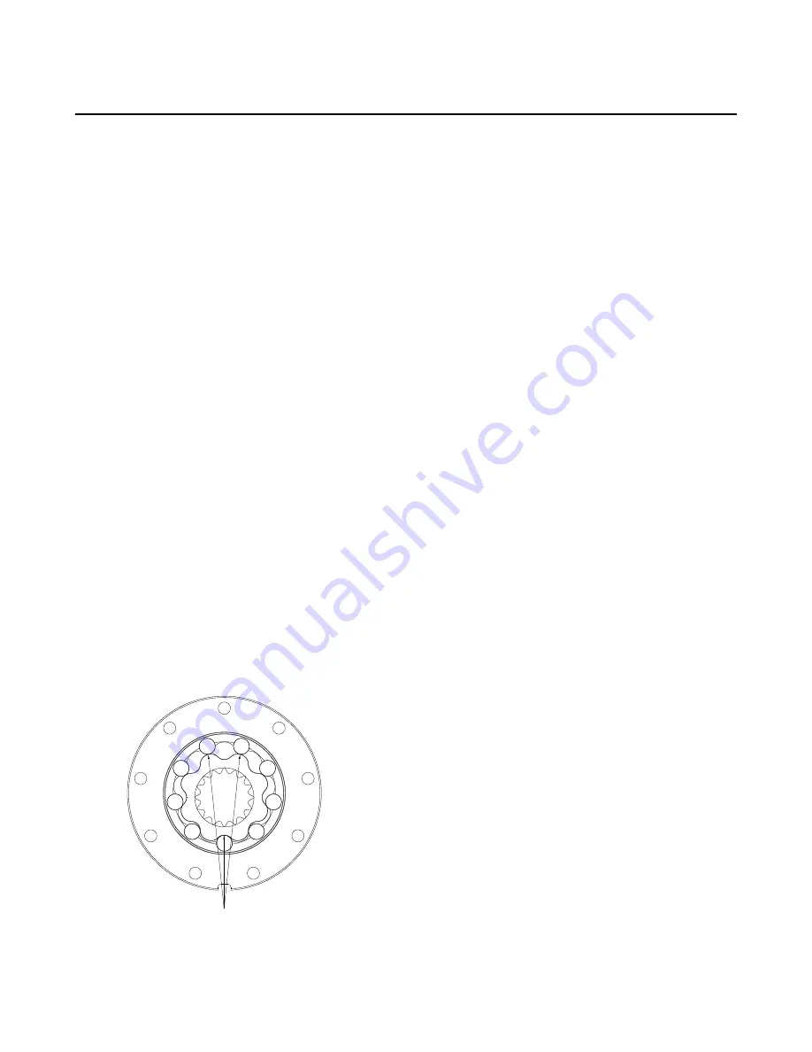
Place body seals (7) in grooves in both sides of rotor set (14). Place rotor set (14) onto wear plate (13) with I.D.
spline chamfer facing wear plate. See below for rotor assembly timing.
Figure 1: D9 Rotor Assembly Timing Position
Orbital Motors | D9 800 & 801 Series Service Instructions |
10
Summary of Contents for D9 01 Series
Page 1: ...Repair Instructions D9 800 801 Series...
Page 2: ......
Page 4: ......
Page 5: ...Chapter 1 D9 800 801 Series Diagram Topics D9 800 801 Series Exploded View...
Page 8: ......
Page 13: ...Chapter 3 D9 800 801 Series Parts Listing Topics D9 800 801 Series Replacement Kits...
Page 18: ......