background image

17

Model SB45 & SB55

Ref. 

No.

Part No.

Part Description

1.

705-5139

Support Bracket, Gas Tank

2.

710-0157

Hex Cap Screw 5/16-24 x 0.75”

4.

710-3013

Hex Screw 1/4-20 x 0.50”

5.

710-0896

Washer Screw 1/4-14 x 0.625”

6.

710-3025

Hex Cap Screw 5/16-24 x 
0.625”

7.

726-0205

Hose Clamp

8.

736-0119

Lock Washer

9.

736-0242

Bell Washer

10.

736-0329

Lock Washer

11.

741-0475

Plastic Bushing

12.

751-0535-
16

Hose, Fuel Line—16”

13.

751-0540A

Fuel Tank—2 qt.

14.

751-0800

Fuel Cap

15.

754-0101A

V-Belt

16.

756-0416B

V-Pulley Half

17.

756-0475

V-Pulley Half

18.

629-0236

Cord, Extension

19.

Obtain from engine 
manufacturer

Ref. 

No.

Part No.

Part Description

18

Summary of Contents for SB 45

Page 1: ...rass covered land unless the engine s exhaust system is equipped with a spark arrester meeting applicable local or state laws if any If a spark arrester is used it should be maintained in effective working order by the operator In the State of California the above is required by law Section 4442 of the California Public Resources Code Other states may have similar laws Federal laws apply on federa...

Page 2: ...our Customer Referral Line or an authorized dealer You can locate the model number by standing behind the unit in the operating position and looking down at the dash panel A sample model plate is explained below For future reference please copy the model number and the serial number of the equipment in the space below CALLING CUSTOMER SUPPORT If you have difficulty assembling this product or have ...

Page 3: ...r other loose clothing which could become entangled in moving parts Wear footwear which will improve footing on slippery surfaces Before working with gasoline extinguish all cigarettes and other sources of ignition Check the fuel before starting the engine Gasoline is an extremely flammable fuel Do not fill the gasoline tank indoors while the engine is running or until engine has been allowed to c...

Page 4: ...as wheel weights counter weights cabs etc Never operate the snow thrower without good visibility or light Always be sure of your footing and keep a firm hold on the handles Walk never run Muffler and engine become hot and can cause a burn Do not touch Maintenance And Storage Check shear bolts engine mounting bolts etc at frequent intervals for proper tightness to be sure equipment is in safe worki...

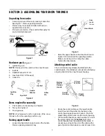
Page 5: ...ure 3 Raise the upper handle in the direction shown in Figure 3 till it clicks into the operating position Make sure not to pinch or crimp the cable Tighten the hand knobs Attaching control cable The control cable may already be attached to the control handle If not attached complete the following steps to attach it to the snow thrower housing Figure 4 Route the control cable over the lower handle...

Page 6: ...n opposite directions to secure See Figure 6 Figure 6 Secure eyebolt with 5 16 saddle washer and hex nut The cupped side of washer goes against the handle Adjust lower hex nut until the eyebolt is positioned so that the chute crank turns freely does not bind Move upper hex nut down against the lower handle Tighten lower hex nut securely Assembling the chute The snow thrower has been shipped with t...

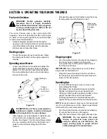
Page 7: ...rmines the direction that snow will be discharged Turn clockwise to discharge snow to the left turn counterclockwise to discharge to the right Discharge Chute The angle of the discharge chute controls the distance that the snow is thrown Tilt the discharge chute up for greater distance tilt down for less distance Loosen the hand knob on the side of the discharge chute to adjust Tilt the chute to t...

Page 8: ...th to be cleared Release the auger control handle to stop the snow throwing action and the forward motion Figure 11 Stopping engine Run the engine for a few minutes before stopping to help dry up any moisture on the engine Turn ignition key to OFF position and remove it from the snow thrower IMPORTANT Keep the ignition key in a safe place Engine will not start without it Wipe all snow and moisture...

Page 9: ...iodic adjustment of the belt tension may be required due to normal stretch and wear on the belt Adjust the belt tension following instructions below if the augers seem to hesitate while turning although engine maintains the same speed The upper hole in the control handle provides adjustment for belt tension To adjust disconnect the Z end of control cable from the bottom hole in the control handle ...

Page 10: ...e pulley Push down on the idler pulley and slip the belt off the auger pulley Reassemble new belt in reverse order Reinstall the belt cover Figure 17 Replacing shave plate The shave plate is subject to wear It should be checked periodically There are two wearing edges and the shave plate can be reversed See Figure 18 Remove the four carriage bolts and hex lock nuts which attach it to the snow thro...

Page 11: ...the snow thrower at the end of the season SECTION 8 OFF SEASON STORAGE WARNING Never store engine with fuel in tank indoors or in enclosed poorly ventilated areas where fuel fumes may reach an open flame spark or pilot light as on a furnace water heater clothes dryer or other gas appliance Clean snow thrower thoroughly Lubricate as instructed above with a light oil Follow Storage instructions foun...

Page 12: ...ed service dealer Engine overheats 1 Gasoline and oil not mixed correctly 2 Carburetor out of adjustment 1 Drain fuel tank and refill with proper fuel mixture 2 Refer to engine manual get the carburetor adjusted by an authorized service dealer Loss of power 1 Spark plug wire loose 2 Vent in gas cap plugged 3 Exhaust port plugged 1 Connect and tighten spark plug wire 2 Clear vent 3 Clean port Exces...

Page 13: ...13 SECTION 10 PARTS LIST FOR MODEL SB45 SB55 34 27 1 6 13 20 23 33 17 8 19 29 24 10 10 7 22 2 32 21 14 2 14 15 24 29 10 30 25 11 17 8 3 28 12 26 18 13 31 5 9 35 ...

Page 14: ... Nut 13 712 3010 Hex Nut 14 712 3027 Hex Flange Lock Nut 15 731 1033 Shave Plate 16 732 0357A Extension Spring 17 736 0108 Flat Washer 18 736 0119 Lock Washer 19 736 0176 Flat Washer 20 736 0242 Belleville Washer 21 736 0326 Flat Washer 22 736 0329 Lock Washer 23 741 0475 Bushing 24 741 0600 Ball Bearing 25 746 0910A Clutch Cable 26 748 0234 Spacer 27 749 0796 Lower Handle 28 756 0313 Idler Flat 2...

Page 15: ... Lower Chute 9 731 0921 Upper Chute 10 736 0159 Washer Model SB45 SB55 Ref No Part No Description 1 710 0487 Carriage Screw 5 16 18 x 2 0 2 710 1270 Oval C Sunk Screw 1 4 20 x 1 31 3 712 0324 Hex Lock Nut 1 4 20 4 720 0284 Handle Knob 5 720 0295 Foam Grip Handle 6 725 0157 Cable Tie 7 736 0451 Saddle Washer 8 746 0883 Cable Housing 9 747 0956 Auger Handle Gull Wing 10 749 0711A Upper Handle Gull W...

Page 16: ...Key 13 725 1341B Ignition Key w o Logo 14 725 1346 Ignition Switch Nut 15 725 1347 Ignition Switch Cap 16 725 1425 Switch Key Recoil Start 17 726 0100 Push Cap 18 731 1089A Choke Cover 19 731 1133B Cap 20 731 1551A Engine Shroud Grey 21 735 0234 Rubber Grommet 22 736 0119 Lock Washer 23 736 0185 Flat Washer 24 736 0225 Internal Lock Washer 25 736 0451 Saddle Washer 26 747 0697 Eye Bolt 27 747 0737...

Page 17: ... 3025 Hex Cap Screw 5 16 24 x 0 625 7 726 0205 Hose Clamp 8 736 0119 Lock Washer 9 736 0242 Bell Washer 10 736 0329 Lock Washer 11 741 0475 Plastic Bushing 12 751 0535 16 Hose Fuel Line 16 13 751 0540A Fuel Tank 2 qt 14 751 0800 Fuel Cap 15 754 0101A V Belt 16 756 0416B V Pulley Half 17 756 0475 V Pulley Half 18 629 0236 Cord Extension 19 Obtain from engine manufacturer Ref No Part No Part Descrip...

Page 18: ...18 Your Notes Dates ...

Page 19: ...19 Your Notes Dates ...

Page 20: ...arranty Please refer to the applicable manufacturer s warranty on these items b Log splitter pumps valves and cylinders have a sepa rate one year warranty c Routine maintenance items such as lubricants filters blade sharpening and tune ups or adjustments such as brake adjustments clutch adjustments or deck adjustments and normal deterioration of the exterior finish due to use or exposure d White O...

Reviews: