background image

12

Remove the hairpin clips from the weld pins on the 
handle brackets. Press outward on the legs of the 
lower handle, and remove it from the mower.

Turn the lower handle around so the notches on the 
bottom of the lower handle are facing forward as 
shown in Figure 11. Reassemble, placing the 
bottom holes in the handle over the weld pins in the 
handle mounting bracket.

Reassemble the upper handle.

Place the hairpin clips in the inner holes in the weld 
pins and attach the starter rope as instructed in the 
assembly instructions.

Cutting Height 

An adjusting plate and thumb lever at each wheel 
position provides cutting height adjustment. Each 
adjusting plate has nine height positions. Height of cut 
will be changed when the thumb lever is moved from 
one hole to another. 

Simply depress the lever towards wheel and move 
wheel and lever assembly to desired position. All 
wheels must be placed in the same relative 
position. See Figure 12.

Figure 12

Adjusting Drive Clutch Control

The drive clutch adjustment wheel is located on the 
drive clutch control handle housing and is used to 
tighten or loosen tension on the drive cable. Perform 
this adjustment if the following exists.

a.

The mower does not propel itself with the drive 
clutch engaged.

b.

The mower’s drive wheels hesitate with the 
drive clutch engaged. 

To resolve the above problems, rotate the 
adjustment wheel with your fingers: clockwise to 
tighten the cable, and counter-clockwise to loosen 
the cable. See Figure 13.

Figure 13

SECTION 7:  MAINTAINING YOUR LAWN MOWER

Replacing Rear Flap 

To remove rear flap, cut off the flat end of the wire 
rod which secures it to the deck. See Figure 14. 

Attach the new flap and new rod to deck, bending 
the ends of the new rod over to secure to deck.

Figure 14

Deck Care

NOTE:  We do not recommend the use of pressure
washers or garden hose to clean your unit.These may
cause damage to electric components, spindles,
pulleys, bearings or the engine. The use of water will
shorten life of the mower and reduce its serviceability.  

The underside of the mower deck should be 
cleaned after each use to prevent a build-up of 
grass clippings, leaves, dirt or other matter. If this 
debris is allowed to accumulate, it will invite rust 
and corrosion, and may cause an uneven 
discharge of grass clippings at the next cutting.

The deck may be cleaned by tilting the mower and 
scraping clean with a suitable tool (make certain the 
spark plug wire is disconnected).

Height

Adjustment

Lever

To tighten 
cable

To loosen
cable

Adjustment
Wheel

Handle
Bracket

Handle
Bracket

Rear Discharge 
Door

Rear 

Wi

re 

Ro

d

Flap

Summary of Contents for HW-656

Page 1: ...tem is equipped with a spark arrester meeting ap plicable local or state laws if any If a spark arrester is used it should be maintained in effective working order by the operator In the State of California the above is required by law Section 4442 of the California Public Resources Code Other states may have similar laws Federal laws apply on federal lands A spark arrester for the muffler is avai...

Page 2: ...ler Referral Line or an authorized White Outdoor dealer You can locate the model number by standing at the operating position and looking down at the rear of the mower A sample model plate is explained below For future reference please copy the model number and the serial number of the equipment in the space below CALLING CUSTOMER SUPPORT If you have difficulty assembling this product or have any ...

Page 3: ...en overlooked and could be accidentally thrown by the mower in any direction and cause serious personal injury to the operator or any others allowed in the area Wear sturdy rough soled work shoes and close fitting slacks and shirts Shirts and pants that cover the arms and legs and steel toed shoes are recommended Do not wear loose fitting clothes or jewelry They can be caught in moving parts Never...

Page 4: ... seconds Do not Do not mow near drop offs ditches or embankments The operator could lose footing or balance Do not mow slopes greater than 15 degrees as shown on the slope gauge Do not mow on wet grass Reduced footing could cause slipping Children Tragic accidents can occur if the operator is not alert to the presence of children Children are often attracted to the mower and the mowing activity Ne...

Page 5: ...or cutting height adjustment while the engine is running Grass catcher components are subject to wear damage and deterioration which could expose moving parts or allow objects to be thrown For safety protection frequently check components and replace with manufacturer s recommended parts when necessary Mower blades are sharp and can cut Wrap the blade s or wear gloves and use extra caution when se...

Page 6: ... DETERMINE SLOPES WHERE YOU MAY NOT OPERATE SAFELY Do not mow on inclines with a slope in excess of 15 degrees a rise of approximately 2 1 2 feet every 10 feet A riding mower could overturn and cause serious injury If operating a walk behind mower on such a slope it is extremely difficult to maintain your footing and you could slip resulting in serious injury Operate RIDING mowers up and down slop...

Page 7: ...ut of the way See Figure 2 step 1 Raise the lower handle in the direction shown in Figure 2 step 2 till it snaps into place Raise the upper handle in the direction shown in Figure 2 step 3 Tighten the wing nuts which are already on the handle Figure 2 NOTE Your mower is shipped with the handle in the higher height position If you wish to lower the height of the handle refer to the Adjustment Secti...

Page 8: ...n you are not mulching the grass To remove the mulching baffle lift the rear discharge door on the mower Remove the mulching baffle See Figure 7 Figure 7 IMPORTANT Make sure cables are routed to the outside of the handle so they are not in the way when attaching the grass catcher Lift the rear discharge door on the mower Place the hooks found on both sides of the grass catcher frame over the chute...

Page 9: ...s a safety device Never attempt to bypass its operations The blade control handle is located on the upper handle of the mower and must be depressed in order to operate the unit Release it to stop engine and blade Recoil Starter The recoil starter handle is attached to the handle and is used to start the engine Grass Catcher The grass catcher located at the rear of the mower is used to bag the gras...

Page 10: ...ine running or until the engine has been allowed to cool for at least two minutes after running Adjusting Cutting Height Your mower was shipped at the highest cutting height For best results in mowing keep the cutting height position high until it is determined which height is best for your lawn Refer to height adjustments section of this manual on page 12 for instruction on how to adjust the cutt...

Page 11: ... and do the most effective job of bagging the cut grass WARNING If you strike a foreign object stop the engine Remove wire from spark plug and ground it Thoroughly inspect the mower for any damage and repair the damage before restarting and operating the mower again Using the Mulcher For effective mulching do not cut wet grass because it tends to stick to the underside of the deck preventing prope...

Page 12: ...r does not propel itself with the drive clutch engaged b The mower s drive wheels hesitate with the drive clutch engaged To resolve the above problems rotate the adjustment wheel with your fingers clockwise to tighten the cable and counter clockwise to loosen the cable See Figure 13 Figure 13 SECTION 7 MAINTAINING YOUR LAWN MOWER Replacing Rear Flap To remove rear flap cut off the flat end of the ...

Page 13: ...erate freely in both directions Rear Side Discharge Doors The torsion springs and pivot points should be lubricated periodically with light oil to prevent any rust or binding Door must work freely Wheels The wheels require no lubrication However if the wheels are removed for any reason lubricate the surface of the axle bolt and the inner surface of the wheel with light oil Engine oil may also be u...

Page 14: ... to prevent an unbalanced blade NOTE An unbalanced blade will cause excessive vibration when rotating at high speeds may cause damage to the mower and could break causing personal injury The blade can be tested by balancing it on a round shaft screwdriver See Figure 17 Remove metal from the heavy side until it balances evenly It is recommended that the blade always be removed from the adapter for ...

Page 15: ...spark plug 9 Engine flooded 1 Engage blade control handle 2 Connect wire to spark plug 3 Refer to the engine manual 4 Refer to the engine manual 5 Move throttle lever to FAST or START position 6 Clean fuel line 7 Clean adjust gap or replace 8 Refer to the engine manual 9 Wait for a while and crank the engine Engine runs erratic 1 Unit running in START position 2 Spark plug wire loose 3 Blocked fue...

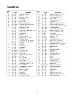
Page 16: ...4 78 73 7 45 75 74 76 31 30 29 9 18 77 23 79 46 46 22 22 NOTE For painted parts please refer to the list of color codes below Please add the applicable color code wherever needed to the part number to order a replacement part For instance if a part numbered 700 xxxx is painted Oyster Gray the part number to order would be 700 xxxx 0662 Oyster Gray 0662 Powder Black 0637 Red Metallic 0650 80 81 82 ...

Page 17: ...2 0741 21 Mulching Blade 42 736 0452 Flat Washer 516 x 1 5 x 134 43 710 0606 Hex Screw 1 4 20 x 1 50 44 710 1257 Hex Screw 3 8 24 x 2 50 45 749 0907A Lower Handle 46 710 0703 Carriage Bolt 1 4 20 x 75 52 712 0798 Hex Nut 3 8 16 53 736 0356 Bell Washer 39 I D x 1 38 O D 54 712 3005 Hex Flange Lock Nut 3 8 16 55 710 0896 Hex Scr w Washer 1 4 14 x 625 56 682 3056A RH Handle Bracket 682 3057A LH Handl...

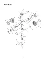
Page 18: ... 5 6 7 8 9 10 11 13 12 15 16 30 31 32 33 35 36 38 41 40 39 42 43 45 51 55 14 30 31 32 33 39 34 37 36 40 41 42 43 44 51 46 52 53 47 17 21 19 20 20 19 22 23 24 25 26 27 50 54 28 28 46 52 53 47 49 48 29 Model HW 656 ...

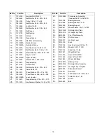
Page 19: ...736 0569 Thrust Washer 388 x 625 x 062 26 618 0299A Lower Housing 27 741 0672 Flange Bearing 378 x 531 x 370 28 710 1276 Hex Screw w Washer 1 4 20 x 750 29 618 0298A Transmission Assembly Includes Ref 1to Ref 30 30 732 0708 Bearing Retainer 31 741 0604 Bearing Sleeve 50 I D 32 748 0355 Bearing Support 33 736 0447 Wave Washer 1 5 x 1 0 x 029 34 782 0512B RH Height Adj Plate 35 782 0511A LH Height A...

Page 20: ... these items b Routine maintenance items such as lubricants filters blade sharpening and tune ups or adjustments such as brake adjustments clutch adjustments or deck adjustments and normal deterioration of the exterior finish due to use or exposure c Log splitter pumps valves and cylinders have a sepa rate one year warranty d White Outdoor Co does not extend any warranty for products sold or expor...

Reviews: