background image

Driving On Slopes

3FGFSUPUIF4-01&("6(&POQBHFUPIFMQEFUFSNJOFTMPQFT

where you may operate the tractor safely.

8"3/*/(

Do not mow on inclines with a slope in 

excess of 15 degrees (a rise of approximately 2-1⁄2 
feet every 10 feet). The tractor could overturn and 
cause serious injury.

.PXVQBOEEPXOTMPQFT/&7&3BDSPTT

t

Exercise extreme caution when changing direction on 

t

slopes.

Watch for holes, ruts, bumps, rocks, or other hidden 

t

objects. Uneven terrain could overturn the machine. Tall 
grass can hide obstacles.

"WPJEUVSOTXIFOESJWJOHPOBTMPQF*GBUVSONVTUCF

t

made, turn down the slope. Turning up a slope greatly 
increases the chance of a roll over.

"WPJETUPQQJOHXIFOESJWJOHVQBTMPQF*GJUJTOFDFTTBSZ

t

to stop while driving up a slope, start up smoothly and 
carefully to reduce the possibility of flipping the tractor 
over backward.

Engaging the Parking Brake/ 
Setting the Cruise Control

NOTE: 

The parking break and cruise control are controlled by 

the same lever. If using the brake when engaging the parking 
brake/cruise control lever, the parking brake will engage. If using 
the drive pedal when engaging the parking brake/cruise control 
lever, the cruise control will engage.

Parking Brake

NOTE: 

The parking brake must be set if the operator leaves the 

seat with the engine running or the engine will automatically 
shut off.

To set the parking brake:

1SFTTUIFCSBLFQFEBMDPNQMFUFMZEPXOXJUIZPVSMFGUGPPU

1. 

and hold it in that position. 

1VTIUIFQBSLJOHCSBLFMFWFSEPXOXBSEBOEIPMEJUJOUIBU

2. 

position.

Remove your foot from the brake pedal.

3. 

Release pressure from the parking brake lever.

"GUFSDPNQMFUJOHTUFQUIFCSBLFQFEBMTIPVMESFNBJOJOUIF
EPXOQPTJUJPO*GJUEPFTOUUIFQBSLJOHCSBLFJT

not

 engaged. 

3FQFBUTUFQTUISPVHIUPFOHBHFUIFQBSLJOHCSBLF

To disengage the parking brake, lightly press the brake pedal .

8"3/*/(

/FWFSMFBWFBSVOOJOHNBDIJOF

VOBUUFOEFE"MXBZTEJTFOHBHF150TFUQBSLJOH

brake, stop engine and remove key to prevent 
unintended starting 

Setting The Cruise Control

8"3/*/(

/FWFSFOHBHFUIFDSVJTFDPOUSPMMFWFS

while traveling in reverse. 


To set the cruise control:

Slowly press the drive pedal until the desired speed is 

1. 

achieved.

Lightly press the cruise control lever downward and hold it 

2. 

in that position.

NOTE: 

$SVJTFDPOUSPMDBOOPUCFTFUBUUIFUSBDUPSTGBTUFTU

ground speed. If the operator should attempt to do so, the 
tractor will automatically decelerate to the fastest optimal 
mowing ground speed

Remove your foot from the drive pedal.

3. 

Release pressure from the cruise control lever

"GUFSDPNQMFUJOHTUFQUIFESJWFQFEBMTIPVMESFNBJOJOUIF

down position and the tractor will maintain the same forward 

TQFFE*GJUEPFTOUUIFDSVJTFDPOUSPMJT

not

 engaged. Repeat 

TUFQTUISPVHIUPFOHBHFUIFDSVJTFDPOUSPM

To disengage the cruise control, lightly press the drive pedal or 
the brake pedal.

To change the direction of travel from forward to reverse when 
cruise control is engaged, press the brake pedal to disengage 
the cruise control and bring the tractor to a complete stop. Then 
place the shift lever in the REVERSE position and depress the 
drive pedal.

Using the Deck Lift Lever

To raise the cutting deck, move the deck lift lever to the left, then 
place it in the notch best suited for your application.

Operating the Headlights

5IFMBNQTBSF0/XIFOFWFSUIFJHOJUJPOLFZJTSPUBUFEPVUPG
UIF4501QPTJUJPO5IFMBNQTUVSO0''XIFOUIFJHOJUJPOLFZJT
NPWFEUPUIF4501QPTJUJPO

S

ECTION

 5 — O

PERATION

Summary of Contents for 90G series

Page 1: ...4FU 6Q t 0QFSBUJPO t BJOUFOBODF t 4FSWJDF t 5SPVCMFTIPPUJOH t 8BSSBOUZ 8 3 3 0 08 4 5 36 4 4536 5 0 4 5 4 6 03 55 15 50 01 3 5 5 4 63 50 0 1 8 5 5 4 4536 5 0 4 3 46 5 1 340 63 PEFM 4FSJFT VUP SJWF BXO 5SBDUPS 1 0 PY FOU WFOVF 5 3 0 5 3 0 769 05536 1 5 10 OUTDOOR ...

Page 2: ...time of printing Review this manual frequently to familiarize yourself with the machine JUT GFBUVSFT BOE PQFSBUJPO 1MFBTF CF BXBSF UIBU UIJT 0QFSBUPS T Manual may cover a range of product specifications for various models Characteristics and features discussed and or illustrated in this manual may not be applicable to all models The manufacturer reserves the right to change product specifications ...

Page 3: ...U JO NPWBCMF QBSUT FWFS PQFSBUF UIJT NBDIJOF JO bare feet or sandals F BXBSF PG UIF NPXFS BOE BUUBDINFOU EJTDIBSHF EJSFDUJPO 10 and do not point it at anyone Do not operate the mower without the discharge cover or entire grass catcher in its proper place Do not put hands or feet near rotating parts or under the 11 cutting deck Contact with the blade s can amputate hands and feet NJTTJOH PS EBNBHFE...

Page 4: ...the slope or if you feel uneasy on it do not mow it For your safety use the slope gauge included as part of this manual to measure slopes before operating this machine on a sloped or hilly area If the slope is greater than 15 degrees as shown on the slope gauge do not operate this machine on that area or serious injury could result Do Mow up and down slopes not across Exercise extreme 1 caution wh...

Page 5: ...en practical remove gas powered equipment c from the truck or trailer and refuel it on the ground If this is not possible then refuel such equipment on a trailer with a portable container rather than from a gasoline dispenser nozzle FFQ UIF OP MF JO DPOUBDU XJUI UIF SJN PG UIF GVFM d tank or container opening at all times until fueling is complete Do not use a nozzle lock open device Extinguish al...

Page 6: ...FDUJPO HFODZ 1 this product has an Average Useful Life PG TFWFO ZFBST PS IPVST PG PQFSBUJPO U UIF FOE PG UIF Average Useful Life have the machine inspected annually by an authorized service dealer to ensure that all mechanical and safety systems are working properly and not worn excessively Failure to do so can result in accidents injuries or death Do not modify engine To avoid serious injury or d...

Page 7: ...utting deck Contact with the blade s can amputate hands and feet 8 3 5 308 0 54 This machine may pick up and throw and objects which can cause serious personal injury 8 3 5 308 0 54 This machine may pick up and throw and objects which can cause serious personal injury 45 34 FFQ CZTUBOEFST IFMQFST DIJMESFO BOE QFUT BU MFBTU GFFU GSPN UIF NBDIJOF XIJMF JU JT JO operation 8 3 4 01 01 3 5 0 Do not ope...

Page 8: ... s e n t s a 1 5 s l o p e 15 Use this page as a guide to determine slopes where you may not operate safely 8 3 Do not operate your lawn mower on such slopes Do not mow on inclines with a slope in excess of 15 degrees B SJTF PG BQQSPYJNBUFMZ GFFU FWFSZ GFFU SJEJOH NPXFS DPVME PWFSUVSO BOE DBVTF TFSJPVT JOKVSZ 0QFSBUF SJEJOH mowers up and down slopes never across the face of slopes ...

Page 9: ...ing brake and remove the ignition key before removing the shipping brace Locate the shipping brace if present and warning tag 1 found on the right side of the cutting deck See Fig 3 1 While holding the discharge chute with your left hand 2 remove the shipping brace with your right hand by grasping it between your thumb and index finger and rotating it clockwise WARNING The shipping brace is used f...

Page 10: ...0QFSBUPS T BOVBM QSJPS UP PQFSBUJOH the tractor Checking Tire Pressure 8 3 Do not overinflate tires Check sidewall of tires for maximum psi Equal tire pressure should be maintained at all times The tires on your tractor may be over inflated for shipping purposes Reduce the tire pressure before operating the tractor Check sidewall of tires for maximum psi Setting the Deck Gauge Wheels Move the trac...

Page 11: ...seat until it clicks into place Gas and Oil Fill up 8 3 Use extreme care when handling HBTPMJOF BTPMJOF JT FYUSFNFMZ GMBNNBCMF BOE UIF WBQPST BSF FYQMPTJWF FWFS GVFM NBDIJOF JOEPPST PS while the engine is hot or running Extinguish cigarettes cigars pipes and other sources of ignition Service the engine with gasoline and oil as instructed in the separate Engine Operator Owner Manual packed with you...

Page 12: ...sition JHVSF Brake Pedal The brake pedal is located on the left front side of the tractor along the running board The brake pedal can be used for sudden stops or setting the parking brake NOTE The brake pedal must be fully depressed to activate the safety interlock switch when starting the tractor Seat Adjustment Lever The seat adjustment lever is located under the front of the seat To adjust the ...

Page 13: ...ctor operation Once the tractor is started the monitor continually displays an hour glass and the hours of tractor operation on its LCD NOTE PVST PG USBDUPS PQFSBUJPO BSF SFDPSEFE BOZ UJNF UIF JHOJUJPO LFZ JT SPUBUFE PVU PG UIF 4501 QPTJUJPO SFHBSEMFTT PG whether the engine is started The Indicator Monitor will also remind the operator of maintenance intervals for changing the engine oil The LCD w...

Page 14: ...PDBUFE JO UIF DFOUFS PG UIF USBDUPS T EBTI QBOFM CFMPX UIF TUFFSJOH XIFFM UIF 1BSLJOH SBLF SVJTF POUSPM MFWFS JT VTFE to engage the parking brake and the cruise control Refer to the Operation section of this manual for detailed instructions regarding the parking brake NOTE The parking brake must be set if the operator leaves the seat with the engine running or the engine will automatically shut of...

Page 15: ...ning This system was designed for your safety and protection NOTE Refer to the Gasoline and Oil fill up instructions in the Assembly Set up section of this manual Insert the tractor key into the ignition switch module 1 Place the PTO Blade Engage lever in the disengaged OFF 2 position Engage the tractor s parking brake 3 Activate the choke control by moving the throttle choke 4 control all the way...

Page 16: ...PS UP CF PQFSBUFE JO SFWFSTF XJUI UIF CMBEFT 150 engaged NOTE Mowing in reverse is not recommended 8 3 Use extreme caution while operating UIF USBDUPS JO UIF 3 7 34 65 0 0 MXBZT look down and behind before and while backing Do not operate the tractor when children or others are around Stop the tractor immediately if someone enters the area 5P VTF UIF 3 7 34 65 0 0 NOTE The operator MUST be seated ...

Page 17: ...UFQ UIF CSBLF QFEBM TIPVME SFNBJO JO UIF EPXO QPTJUJPO G JU EPFTO U UIF QBSLJOH CSBLF JT not engaged 3FQFBU TUFQT UISPVHI UP FOHBHF UIF QBSLJOH CSBLF To disengage the parking brake lightly press the brake pedal 8 3 FWFS MFBWF B SVOOJOH NBDIJOF VOBUUFOEFE MXBZT EJTFOHBHF 150 TFU QBSLJOH brake stop engine and remove key to prevent unintended starting Setting The Cruise Control 8 3 FWFS FOHBHF UIF DS...

Page 18: ...P BWPJE discharge of materials toward roads sidewalks CZTUBOEFST BOE UIF MJLF MTP BWPJE EJTDIBSHJOH material against a wall or obstruction which may cause discharged material to ricochet back toward the operator Do not mow at high ground speed especially if a mulch kit t or grass collector is installed Do not cut the grass too short Short grass is prone to weed t growth and yellows quickly in dry ...

Page 19: ...all engine maintenance procedures and instructions NOTE Maintenance repair or replacement of the emission DPOUSPM EFWJDFT BOE TZTUFNT XIJDI BSF CFJOH EPOF BU PXOFS T expense may be performed by any engine repair establishment or individual 8BSSBOUZ SFQBJST NVTU CF QFSGPSNFE CZ BO BVUIPSJ FE EFBMFS Changing the Engine Oil 8 3 If the engine has been recently run the engine muffler and surrounding me...

Page 20: ...ry and is maintenance free The fluid level cannot be checked and the fluid cannot be changed Battery 03 130104 5 0 8 3 BUUFSZ QPTUT UFSNJOBMT BOE SFMBUFE BDDFTTPSJFT contain lead and lead compounds chemicals known to the State of California to cause cancer and reproductive harm Wash hands after handling 5IF CBUUFSZ JT TFBMFE BOE JT NBJOUFOBODF GSFF DJE MFWFMT DBOOPU be checked and fluid can not be...

Page 21: ... SFUVSO UP UIF PQFSBUPS T QPTJUJPO BOE FOHBHF UIF 150 FFQ UIF DVUUJOH deck running for a minimum of two minutes allowing the underside of the cutting deck to thoroughly dry Lubrication 8 3 FGPSF MVCSJDBUJOH SFQBJSJOH PS JOTQFDUJOH BMXBZT EJTFOHBHF 150 TFU QBSLJOH brake stop engine and remove key to prevent unintended starting Front Wheels Each of the front wheel axles and rims is equipped with a H...

Page 22: ...hould be between 1 4 inch and 3 8 inch lower than the rear of the deck Adjust if necessary as follows Park the tractor parked on a firm level surface and place 1 the deck lift lever in the top notch Rotate the blade nearest the discharge chute so that it is 2 parallel with the tractor Measure the distance from the front of the blade tip to the 3 ground and the rear of the blade tip to the ground T...

Page 23: ...stment instructions WARNING Before operating the tractor make sure the seat is engaged in the seat stop Engage the parking brake Stand behind the machine and pull back on seat until it clicks into place Steering Adjustment If the tractor turns tighter in one direction than the other or if the ball joints are being replaced due to damage or wear the steering drag links may need to be adjusted Adjus...

Page 24: ...moved from the electric PTO clutch carefully insert a 3 8 drive ratchet wrench set to loosen into the square hole found in the deck idler bracket and pivot it toward the tractor s left side to relieve tension on the belt See Fig 7 2 WARNING Avoid pinching injuries Never place your fingers on the idler spring or between the belt and a pulley while removing the belt Looking at the cutting deck from ...

Page 25: ...BOHFSPVT CZ not disengaging completely For a proper working machine use factory approved belts MM CFMUT PO ZPVS USBDUPS BSF TVCKFDU UP XFBS BOE TIPVME CF replaced if any signs of wear are present To change or replace the deck belt on your tractor proceed as follows Remove the deck as previously instructed 1 Remove the belt covers by removing the hex washer 2 TDSFXT UIBU GBTUFO UIFN UP UIF EFDL 4FF...

Page 26: ...er to 1 Cutting Deck Removal earlier in this section then gently flip the deck over to expose its underside 1MBDF B CMPDL PG XPPE CFUXFFO UIF DFOUFS EFDL IPVTJOH 2 baffle and the cutting blade to act as a stabilizer 4FF JH Remove the hex flange nut that secures the blade to the 3 TQJOEMF BTTFNCMZ 4FF JH To properly sharpen the cutting blades remove equal amounts of metal from both ends of the blad...

Page 27: ...as on a water heater space heater furnace clothes dryer or other gas appliances 65 0 8IFO DIBSHJOH ZPVS USBDUPS T CBUUFSZ use only a charger designed for 12V lead acid CBUUFSJFT 3FBE ZPVS CBUUFSZ DIBSHFS T 0XOFS T BOVBM QSJPS UP DIBSHJOH ZPVS USBDUPS T CBUUFSZ MXBZT GPMMPX JUT JOTUSVDUJPOT BOE IFFE JUT XBSOJOHT If your tractor has not been put into use for an extended period of time charge the bat...

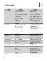
Page 28: ...damaged Drain fuel tank Refill with clean fresh 5 gasoline Replace air cleaner paper element or clean 6 foam precleaner Engine overheats Engine oil level low 1 JS GMPX SFTUSJDUFE 2 Fill crankcase with proper amount and 1 weight of oil Clean grass clippings and debris from around 2 UIF FOHJOF T DPPMJOH GJOT BOE CMPXFS IPVTJOH Engine hesitates at high 31 Spark plug s gap too close 1 Remove spark plu...

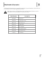
Page 29: ...rice and availability BVUJPO 5IFTF MBXO USBDUPST BSF 05 EFTJHOFE GPS VTF XJUI BOZ UZQF PG HSPVOE FOHBHJOH BUUBDINFOUT F H UJMMFS PS NPMECPBSE QMPX 6TF PG UIJT UZQF PG FRVJQNFOU 8 WPJE UIF USBDUPS T XBSSBOUZ Model Number Description VMDI JU w 5XJO BHHFS w FDL 0 4OPX 5ISPXFS w 0 Wheel Weights 0 w 4OPX MBEF 0 3FBS SBDLFU 8FJHIU JU 0 Tire Chains 20 x 10 SPOU VNQFS Attachments Accessories 9 ...

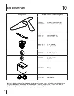
Page 30: ...heel Front 734 0973 Deck Wheel Rear optional 725 1707D Battery 751 0603A Fuel Tank Cap NOTE This Operators Manual covers a range of product specifications for various models Characteristics and features discussed and or illustrated in this manual may not be applicable to all models The manufacturer reserves the right to change product specifications designs and equipment without notice and without...

Page 31: ...s 725 1745A Ignition Key 631 04349 Discharge Chute Assembly 42 46 NOTE Download a complete Parts Manual refer to customer support on page 2 Be sure to have your model number and serial number ready These can be found on the model plate located under the seat Refer to page 2 for more information regarding locating your model and serial numbers SECTION 10 REPLACEMENT PARTS ...

Page 32: ... Inc s application for certification The warranty period begins on the date the lawn mower is delivered to an ultimate purchaser or first placed into service The warranty period is two years Subject to certain conditions and exclusions as stated below the warranty on emission related parts is as follows 1 Any warranted part that is not scheduled for replacement as required maintenance in the writt...

Page 33: ...stem s OLD START ENRICHMENT SYSTEM SOFT CHOKE s ARBURETOR AND INTERNAL PARTS s UEL PUMP s UEL TANK 2 Air Induction System s IR CLEANER s NTAKE MANIFOLD 3 Ignition System s 3PARK PLUG S s AGNETO IGNITION SYSTEM 4 Exhaust System s ATALYTIC CONVERTER s 3 2EED VALVE 5 Miscellaneous Items Used in Above System s 6ACUUM TEMPERATURE POSITION TIME SENSITIVE VALVES AND SWITCHES s ONNECTORS AND ASSEMBLIES 6 ...

Page 34: ...arpening tune ups brake adjustments clutch adjustments deck adjustments and normal deterioration of the exterior finish due to use or exposure d Service completed by someone other than an authorized service dealer e MTD does not extend any warranty for products sold or exported outside of Canada including possessions and territories f Replacement parts that are not genuine MTD parts g Transportati...

Reviews: