background image

Page 18

16938-3-0806

CIVF-25 ON/OFF/REMOTE Switch

CIVF-25 is equipped with an ON/OFF/REMOTE switch which 

is located on the wire channel. A wire harness is attached to the 

ON/OFF/REMOTE switch. The red, black and green (wires) female 

push-ons attach to the ON/OFF/REMOTE switch. At the opposite 

end of the wire harness, the black and green (wires) female push-

ons attach to the gas valve. An additional green wire and the red 

wire, which are stripped and bare, will attach to the 750 millivolt 

wall thermostat  accessory, or, to one of the other accessories that 

can be purchased for use with your log set. 

Operation of ON/OFF/REMOTE Switch with no Accessories 

To  ignite  main  burner,  turn  the  control  knob  on  the  gas  valve 

from the PILOT position to the ON position. Turn the ON/OFF/

REMOTE switch from the OFF position to the ON position. The 

additional green wire and red wire, which are stripped and bare 

are not used.

Operation of ON/OFF/REMOTE Switch with Accessories

750 Millivolt Wall Thermostat 

Connect the green and red, stripped and bare, wires on the ON/

OFF/REMOTE switch wire harness to the wall thermostat. Turn the 

ON/OFF/REMOTE switch on the wire channel to the REMOTE 

position. Set the wall thermostat to the desired temperature. 
It is important to use wire of a gauge proper for the length of the 

wire:

RECOMMENDED WIRE GAUGES


Maximum 

Wire


Length 

Gauge 


1' to 10' 

18


10' to 25' 

16


25' to 35' 

14

Wall Switch, FWS-1

Connect the green and red, stripped and bare, wires on the ON/OFF/

REMOTE switch wire harness to the wall switch. Turn the ON/OFF/

REMOTE switch on the wire channel to the REMOTE position. 

Pivot the rocker switch on the FWS-1 to the ON position.  

Battery Operated Remote Control, FRBC-1 and FRBTC-1

Connect the green and red, stripped and bare, wires on the ON/

OFF/REMOTE switch wire harness to the remote receiver that is 

a component in the FRBC-1 and FRBTC-1. Turn the ON/OFF/

REMOTE switch on the wire channel to the REMOTE position. 

Follow  instructions  in  the  FRBC-1  and  FRBTC-1  to  complete 

installation. 

Note:

 If batteries fail in FRBC-1 or FRBTC-1, and immediate heat 

is desired, turn the ON/OFF/REMOTE switch on wire channel 

from the REMOTE position to the ON position. 

Electric (120 volt) Operated Remote Control, FREC-1

Connect the green and red, stripped and bare, wires on the ON/OFF/

REMOTE switch wire harness to the wires on remote receiver that 

is a component in the FREC-1. Turn the ON/OFF/REMOTE switch 

on the wire channel to the REMOTE position. Follow instructions 

in the FREC-1 to complete installation.

Note:

 If electric (120 volt) fails in FREC-1, and immediate heat is 

desired, turn the ON/OFF/REMOTE switch on wire channel from 

the REMOTE position to the ON position. 

WIRING

Wiring of ON/OFF/REMOTE Switch with 750 Millivolt Wall 

Thermostat Accessory and Another Accessory

Connect the green and red, stripped and bare, wires on the ON/OFF/

REMOTE switch wire harness to the 750 millivolt wall thermostat 

AND to the remote receiver that is a component in the FRBC-1, 

FREC-1 OR to the FWS-1, wall switch.

1. Connect (1) wire from the 750 millivolt wall thermostat and (1) 

wire from appropriate accessory to the GREEN, stripped and 

bare wire from the ON/OFF/REMOTE wire harness.

2. Connect (1) wire from the 750 millivolt wall thermostat and (1) 

wire from appropriate accessory to the RED, stripped and bare 

wire from the ON/OFF/REMOTE wire harness.

  Note: When the appliance is in the MANUAL mode and the 

batteries fail in the FRBC-1 or if the electric (120 volt) fails in 

the FREC-1, and immediate heat is desired, turn the ON/OFF/

REMOTE switch on wire channel from the REMOTE position 

to the ON position.

Manual Operation

1. Turn ON/OFF/REMOTE switch on wire channel to REMOTE 

position.

2. Turn wall thermostat OFF.

3. Turn accessory, FRBC-1, FREC-1 or FWS-1, ON. Appliance 

is now in the manual mode. You must turn the appliance ON or 

OFF with appropriate accessory.

Wall Thermostat Operation

1. Turn the ON/OFF/REMOTE switch on wire channel to REMOTE 

position.

2. Turn accessory, FRBC-1, FREC-1 or FWS-1, OFF.

3. Turn wall thermostat ON and set appropriate temperature. Wall 

thermostat will cycle the appliance ON and OFF.

Installation of Remote Receiver 

 (Figure 20)

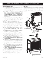
1.  Attach, from left to right, the slide-on cover plate onto the remote 

receiver. 

ON

 will be to the top and 

OFF

 will be to the bottom 

on the slide-on cover plate.

2.  Push the receiver slide button onto the receiver slide switch. 

Reverse installation of the slide button if it is off center.

3.  Attach velcro loop on the left side of the valve cover support.

4.  Attach velcro hook onto remote receiver. The word 

TOP

 on the 

remote receiver should be to the top when installed onto valve 

cover support.

5.  Attach velcro hook on remote receiver onto velcro loop on valve 

cover support.

  Refer to remote control installation and operating instructions 

for more details on remote control.

Figure 20

Summary of Contents for CIVF-25-21

Page 1: ...rmanentlylocated manufactured mobile home where not prohibited by local codes This appliance is only for use with the type of gas indicated on the rating plate This appliance is not convertible for use with other gases The Classic Cast Iron Stoves Do not store or use gasoline or other flamma ble vapors and liquids in the vicinity of this or any other appliance WHAT TO DO IF YOU SMELL GAS Do not try...

Page 2: ...y of Stove Casting 10 12 Optional Stone Inlay Installation 13 Wire Channel Installation 13 Log Placement 14 Operating Guidelines 14 Lighting Instructions 15 Pilot Flame Characteristics 16 Main Burner Flame Characteristics 17 Wiring 18 19 Maintenance 19 Troubleshooting 20 21 How To Order Repair Parts 21 Parts List for Stove Casting 22 Parts List for CIVF 25 21 22 Parts View for Stove Casting 23 Par...

Page 3: ... air opening s of the burner s clean may result in sooting and property dam age Keepapplianceareaclearandfreefromcombustiblemateri als gasoline and other flammable vapors and liquids WARNING Do not use a blower insert heat exchanger insert or other accessory not approved for use with heater THIS IS A HEATING APPLIANCE DO NOT OPERATE THIS APPLIANCE WITHOUT FRONT PANEL INSTALLED When used without ade...

Page 4: ... iron gas pipes Theodorantinescapedgascanadsorborabsorbontoorintowalls masonry and other materials and fabrics in a room That will take some of the odorant out of the gas reducing its odor intensity LP Gas may stratify in a closed area and the odor intensity could vary at different levels Since it is heavier than air there may be more odor at lower levels Always be sensitive to the slightest gas o...

Page 5: ...ing of equipment shall be performed only by a qualified agency The term qualified agency meansanyindividual firm corporationorcompanywhicheitherin person or through a representative is engaged in and is responsible for a the installation or replacement of gas piping or b the connection installation repair or servicing of equipment who is experienced in such work familiar with all precautions required...

Page 6: ...e located and for determining if this area fits the definition of an unconfined space The maximum input of the CIVF 25 is 30 000 Btu per hour Based on the 50 cubic feet per 1 000 Btu per hour formula the minimum area that is an unconfined space for installation of the CIVF 25 is 1 500 cubic feet 50 cubic feet x 30 1 500 cubic feet To determine the cubic feet of the area in which the CIVF 25 is to be i...

Page 7: ...nectors is recommended ANSZ21 24ApplianceConnectorsofCorrugatedMetalTubing and Fittings ANS Z21 45 Assembled Flexible Appliance Connectors of Other Than All Metal Construction The above connectors may be used if acceptable by the authority havingjurisdictionThestateofMassachusettsrequiresthataflexible appliance connector cannot exceed three feet in length Figure 1 Pressure Testing of the Gas Supply...

Page 8: ...te accessibility clearances for purposes of servicing and proper operation must be provided Installation on Rugs and Tile If this appliance is to be installed directly on carpeting tile or other combustible material other than wood flooring the appli ance shall be installed on a metal or wood panel extending the full width and depth of the appliance The base referred to above does not mean the fire ...

Page 9: ... 1 4 20 x 1 Phillips Head Bolt R 3188 4 1 4 20 x 3 8 Phillips Head Bolt R 3646 16 1 4 20 x 1 2 Leveling Bolt R 3747 4 No 10 x 1 2 Hex Washer Head Screw R 2737 10 1 4 20 Washer Head Nut R 3185 4 Leg Pad A see Figure 6 CI 008 2 Leg Pad B see Figure 6 CI 009 2 1 1 4 x 1 2 Retaining Tab see Figure 8 CI 007 4 1 4 x 9 32 Washer Not Shown R 1150 8 ...

Page 10: ...nstructions Follow 3 Refer to Figure 6 the leg pads will have the letter A and B stamped into the metal Place leg pad A and leg pad B at the bottom of each casting side Leg pad A attaches to the front of the casting side right and to the rear of the casting side left Leg pad B attaches to the rear of the casting side right and to the front of the casting side left Position the 3 4 flange on the leg...

Page 11: ...ngintheapproximate location for installation as the completed assembly will be heavy 9 RefertoFigure8 removeprotectivepackingfoamfromcasting front and window Remove the 1 3 4 bolt and 1 1 4 washer from top of window Remove 1 3 8 bolt and 1 5 8 x 3 4 retaining tab from bottom of window Remove the window from casting front Remove the protective sheet of foam from the casting front Place the window i...

Page 12: ...s you completely tighten the 2 3 8 bolts that attach the leg pad to the right casting side Repeat procedure for left front leg to achieve a snug fit between the casting front and the casting side 13 Remove the casting front from the casting 14 Refer to Figures 10 and 11 the appliance firebox can now be inserted into the casting Center the firebox in the casting Attention Remove 1 Phillips head screw ...

Page 13: ...sting 3 Placethecastingtoponanon abrasivesurfaceinordertoprotect the porcelain finish The exterior of the casting top should be facing the non abrasive surface 4 Attach 11 5 8 x 11 5 8 top shield to the interior of the casting top with 1 3 8 bolt provided in hardware package 5 Locate the 4 screw holes on the heat exchanger top The screw holes are 8 3 4 apart Position the angled front edge on the 12...

Page 14: ... the pilot position without pushing the piezo ignitor button at least once every second 2 D u r i n g t h e heating season leavethecontrol valveknobinthe ON position This will allow the pilot flame to remain lit Turn the burner flame on or off with the appliance ON OFF rocker switch wall switch remote control kits or 750 millivolt wall thermostat NOTE Thegascontrolvalveallowsyoutoincreaseordecreaset...

Page 15: ... 6 Wait ten 10 minutes to clear out any gas Then smell for gas including near the floor If you smell gas STOP Fol low B in the safety information above on this plate If you do not smell gas go to the next step 7 Find pilot The pilot is attached to the main burner behind the front log 8 Turn gas control knob counterclockwise to PILOT 9 Push in control knob all the way and hold in Repeatedly push the...

Page 16: ...le to cool When the thermocouple cools the heater will shut down Correct Pilot Flame Pattern Figure 15 Incorrect Pilot Flame Pattern Figure 16 If pilot flame pattern is incorrect as shown in Figure 16 See Troubleshooting pages 20 21 Cleaning and Maintenance Pilot Oxygen Depletion Sensor Pilot Figure 17 When the pilot has a large yellow tip flame clean the Oxygen Depletion Sensor as follows 1 Clean t...

Page 17: ...ervice person should clean dust lint and any light accumulation from the logs and the firebox area An extra soft brush should be used on the logs as they are extremely fragile a vacuum cleaner may be used on the firebox If at any time the logs cannot be removed or installed without forcing the cause must be found The logs must never be forced CAUTION The ceramic logs are durable when handled and ins...

Page 18: ...arness to the wires on remote receiver that isacomponentintheFREC 1 TurntheON OFF REMOTEswitch on the wire channel to the REMOTE position Follow instructions in the FREC 1 to complete installation Note If electric 120 volt fails in FREC 1 and immediate heat is desired turn the ON OFF REMOTE switch on wire channel from the REMOTE position to the ON position WIRING Wiring of ON OFF REMOTE Switch wit...

Page 19: ...hing at least twice a year Cleaning Procedure Figure 22 1 Turn off pilot light at gas valve 2 Remove screen front 2 10 x 1 2 screws 3 Vacuum burner compartment especially around orifice primary air openings 4 Replace screen front 2 10 x 1 2 screws 5 Ignite pilot See Lighting Instructions page 15 6 Operate the main burner and visually check to make sure the flame pattern appears similar to the pictor...

Page 20: ...pilot is lit a Main burner orifice clogged Clean main burner or replace main burner orifice b Main burner orifice diameter is too small Replace main burner orifice c Inlet gas pressure is too low Contact local gas company 5 Pilot burning no gas to burner valve knob ON on off switch ON a On Off switch wall switch remote control or wires defective Check on off switch and wires for proper connections Pla...

Page 21: ...e ODS operates a Not enough fresh air is available Open window and or door for ventilation b Low line pressure Contact local gas company c ODS pilot is partially clogged Clean ODS pilot 14 Gas odor even when control knob is in OFF position a Gas leak Locate and correct all leaks b Control valve defective Replace control valve 15 Gas odor during combustion a Foreign matter between logs and main bur...

Page 22: ...L 10 CI 009 LEG PAD B 2 REQUIRED 11 CI 008 LEG PAD A 2 REQUIRED 12 R 3747 LEVELING BOLT 4 REQUIRED 13 R 3952 LEG 4 REQUIRED BLACK PAINT 13 R 3742 LEG 4 REQUIRED BLACK ENAMEL 13 R 3743 LEG 4 REQUIRED SAND ENAMEL 13 R 3744 LEG 4 REQUIRED GREEN ENAMEL 13 R 3745 LEG 4 REQUIRED RED ENAMEL 13 R 3746 LEG 4 REQUIRED NAVY ENAMEL 14 R 3945 SIDE LEFT BLACK PAINT 14 R 3684 SIDE LEFT BLACK ENAMEL 14 R 3692 SID...

Page 23: ...Page 23 16938 3 0806 PARTS VIEW FOR STOVE CASTING Models CIFB 1 CIPB 1 CIPG 1 CIPS 1 CIPN 1 CIPR 1 ...

Page 24: ...Page 24 16938 3 0806 PARTS VIEW FOR CIVF 25 21 ...

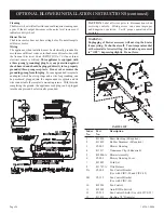
Page 25: ...exchanger top with 4 1 2 hex head screws from Step 6 10 Place the casing top onto the casting The casting top nests into the casting 11 AttachfancontroltoFLAT fancontrolbracket Part9A Page 26 with 2 6 x 1 4 screws provided in hardware package 12 Attachfancontrolwithbracketontothewirechannelbyusing 2 8 x 1 4 screws provided in hardware package 13 Route wires from fan control and ON OFF REMOTE switc...

Page 26: ...to the receptacle mounting screws With this wire completing the ground the appliance cord plug can be plugged into the adapter and be electrically grounded OPTIONAL BLOWER INSTALLATION INSTRUCTIONS continued CAUTION Label all wires prior to disconnection when servicing controls Wiring errors can cause improper and dangerous operation Verify proper operation after servicing WARNING Unplugging of bl...

Page 27: ...Page 27 16938 3 0806 SERVICE NOTES ...

Page 28: ...Page 28 16938 3 0806 Empire Comfort Systems Inc 918 Freeburg Ave Belleville IL 62220 PH 618 233 7420 or 800 851 3153 FAX 618 233 7097 or 800 443 8648 info empirecomfort com www empirecomfort com ...

Reviews: