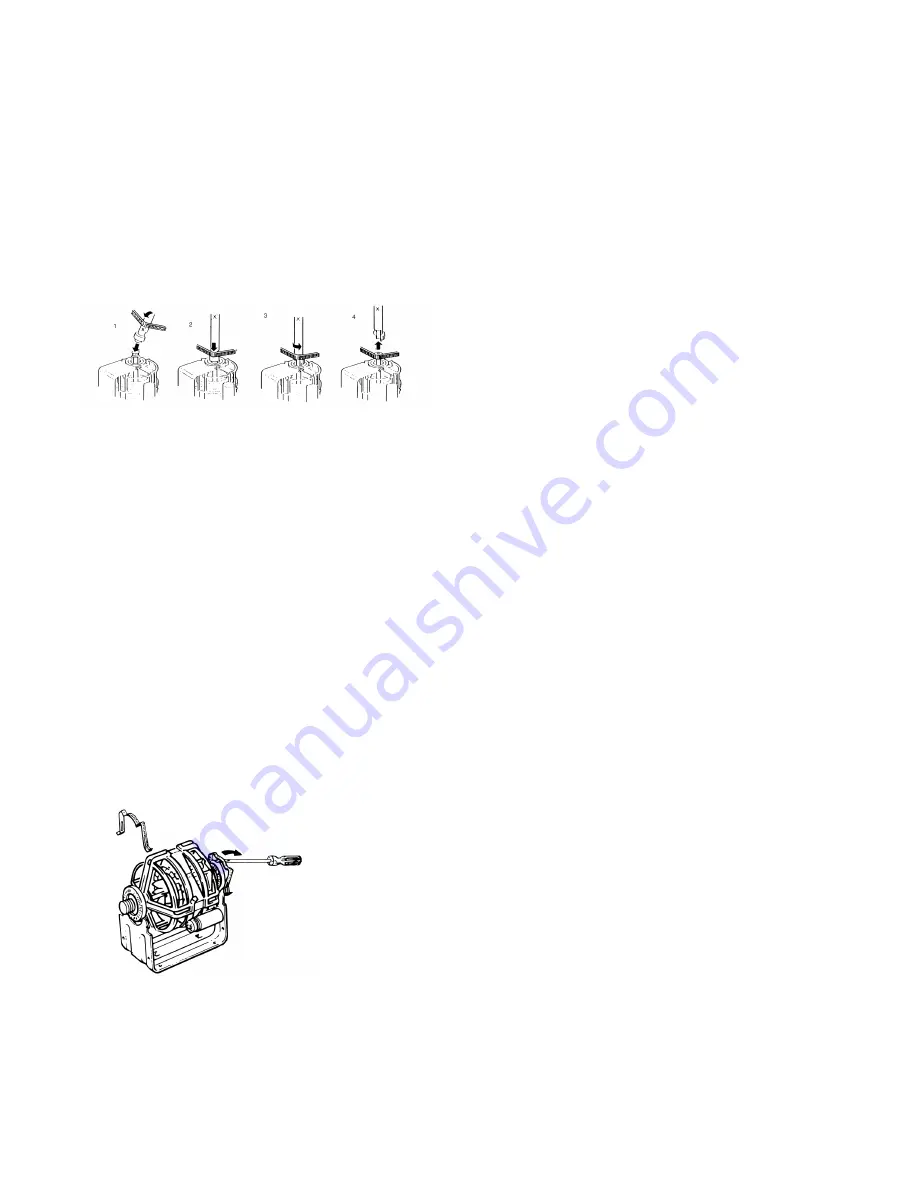
the Fan Access Cover (447) and the back of the Banjo
Assy (440). From underneath the dryer withdraw the 4-
screws (396) securing the Motor Bracket (432) to the
cabinet base. Lift out the Motor and Fan Assy.
Special tool (7813 002 61111) is recommended when
installing a new belt which needs to be levered and
stretched onto the motor spindle (see illustration).
A capacitor (112) is mounted to the motor assembly
Disconnect the wires to the capacitor before removing
the capacitor or the motor capacitor assembly.
The fan (446) is secured to the Motor Shaft by the Spring
Clip (448) and the finger on the Fan Boss must be lifted
before the fan can be withdrawn from the Motor Shaft.
It is important that rigid support is provided to the
motor shaft when the fan is being refitted. This is to
avoid disturbance of the motor bearings from their
location.
On reassembly of the fan access cover (447) it is
important to hold the protruding finger grip at a “2 o-clock”
position to find location. Push the cover fully on to the fan
chamber prior to rotating it clockwise and engaging tightly
in al 3 locations. Re-insert the black headed pin (537).
HEATER ASSEMBLY REMOVAL
Heater Assy. (32), Solenoid Coil (45 or 45A), Flame
failure Electrode (33), lgnition Electrode (39).
Withdraw the 2-screws securing the Plinth (199) to the
Cabinet, unhook the bottom edge fixing, and remove it.
Separate the 4-way Housing (31 ) to release the wiring
from the Heater Assy. to the Cabinet.
Lay the dryer flat on its front, supported to take the
weight from the door and controls.
Withdraw the 6-screws securing the Cover Piate (19) to
the Back Panel (24) and remove it. Pull out the Exhaust
Tube (3o).
Withdraw the 4-screws securing the Hot Air Elbow Assy.
(20) to the Back Panel (24) and remove it.
Disconnect the External Feed Pipe (15) from the Tee
Piece (27).
Pull the connectors off the Flame failure Electrode (33)
and the ignition Electrode (39).
Withdraw the 3-screws and shakeproof vvashers (13)
securing the Flame Tube Assy. (34) to the Cabinet base.
Note:
On re-assembly the shakeproof washers must
be replaced to ensure a good earth connection.
Lift out the Heater Assy.
To remove either solenoid coil (45 or 45A) disconnect
the electrical connectors, unscrew the nut (44).
To remove the sensing electrode (33), withdraw the
screw (41) lockwasher (482) and nut (411 ) securing it
to the Flame Tube Assy. (34). Note on re-assembly the
lockwasher (482) must be replaced to ensure a good
earth connection.
To remove the Ignition Electrode (39), withdraw the
screw securing it to the top of the Heater Tube Assy.
(34).
If there is a fault in the valves, burner or other parts of
the gas line, then the Heater Assy. (32) must be
replaced.
7
TO RELAX
MOTOR CLIPS
Summary of Contents for ECO 83A
Page 12: ...12 Chart 3 Motor runs Full Sequence Control produces ignition sparks but gas does not ignite ...
Page 14: ...14 ...
Page 15: ...15 WHITE KNIGHT ECO 83A_ CROSSLEE P L C EXPLODED VIEW 1 367 ...
Page 17: ...17 WHITE KNIGHT ECO 83A_ CROSSLEE P L C EXPLODED VIEW 3 INTERNALS VIEWED FROM REAR ...
Page 18: ...WHITE KNIGHT ECO 83A_ CROSSLEE P L C EXPLODED VIEW 4 INTERNALS VIEWED FROM REAR 18 ...
Page 19: ...19 WHITE KNIGHT ECO 83A_ CROSSLEE P L C EXPLODED VIEW 5 HEATER ASSEMBLY ...
Page 23: ...23 ...
Page 24: ...Manufactured By Crosslee plc Halifax Road Hipperholme Halifax HX3 8DE 4213 094 79382 ...


