16
Installation and Operation
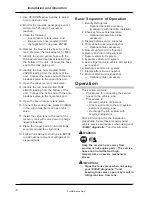
7. Use UP/DOWN arrow buttons to adjust
time to desired value.
8. Monitor the low-side panel gauge until a
minimum of 25 inHg of vacuum is
reached.
9. Close the following:
—
Liquid recovery tank valve, and
—
Blue service hose coupler (CCW).
—
Highlight QUIT and press ENTER.
10. Remove the blue service hose from the
tank. Remove the tank adapter 1-15080.
11. Identify the short, yellow hose with the
Schrader® valve depressor leading from
the bottom of the unit. Connect the hose
end to the tank purge port.
12. Identify the blue hose marked TANK
VAPOR leading from the bottom of the
unit. Connect the hose end with the anti-
blowback valve to the vapor tank port.
13. Open the vapor recovery tank valve.
14. Identify the red hose marked TANK
LIQUID leading from the bottom of the
unit. Connect the hose end with the anti-
blowback valve to the liquid tank port.
15. Open the liquid recovery tank valve.
16. Connect the yellow hose marked VIRGIN
to the virgin tank port and open tank
valve.
17. Install the virgin tank to the rear of the
recovery tank with valve down to charge
liquid refrigerant.
18. Place the longer pair of
Velcro® straps
securely around the virgin tank.
19. Follow
Tank Setup instructions in SETUP
to add nominal amount of refrigerant to
prepared tank.
Basic Sequence of Operation
1. Identify Refrigerant.
—
Optional identifier accessory
(mandatory with identifier installed).
2. Check vehicle vent temperature.
—
Optional temperature probe
accessory.
3. Display before service snapshot.
4. Printout before service snapshot.
—
Optional printer accessory.
5. Recover vehicle A/C refrigerant.
6. Record and drain refrigerant oil.
7. Repair vehicle A/C system.
8. Evacuate vehicle A/C system.
9. Add refrigerant oil to vehicle A/C system
as required.
10. Recharge vehicle A/C system.
11. Display after service snapshot.
12. Printout after service snapshot
—
Optional printer accessory.
Operation
This section contains:
— Procedures for connecting the service
hoses to the vehicle, and
— Procedures to:
• Recover vehicle refrigerant,
• Create a vacuum in the A/C system
before recharging, and
• Recharge the A/C system with
recycled refrigerant.
After performing all of the installation
procedures, follow these recommended
vehicle service procedures when using your
1090AT diagnostic™ unit for A/C work.
WARNING
Keep the service hoses away from
moving or hot engine parts. The service
hoses can not withstand high
temperatures or severe mechanical
stress.
IMPORTANT
• Close the tank valves when not using
your
1090AT diagnostic™ unit.
Leaving tank valves open may result in
refrigerant loss from tank.
For Reference Only


