INTRODUCTION
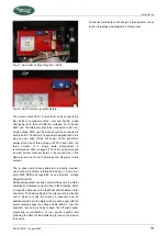
Fig. 2: Location identification plate
2
POWER
The nameplate gives the nominal maximum continues
load in kVA = kW calculated with power factor one.
When calculating a load one should always take into
account the power factor or cos phi of this load. The
power should never exceed the nominal power as
shown on the nameplate. Power is rated at an ambient
temperature of 40°C and a seawater temperature of
25ºC. For higher temperatures the generating set has
to be de-rated.
3
VOLTAGE. This shows the nominal voltage.
This voltage should be within the specified tolerance at
the nominal frequency. The M-SQ27 can be connected
for different voltages in single phase or tri phase. The
nameplate indicates the connection as made in the
factory; BE AWARE THAT THE CONNECTIONS
COULD BE RECONNECTED BY FORMER USERS
4
FREQUENCY. This is shown in Hz and is determined
by the speed of the engine (RPM). 50 Hz correlates
with 1500 rpm.
5
CURRENT. This shows the maximum current that is
acceptable at the specified frequency, voltage and
power factor. When connected in tri phase the
indicated current is the current between two phases
that can be taken off three times.
6
WEIGHT shows the net dry weight (approximately) in
kg. This is without fuel, oil, packing and external
installation equipment
7
CE MARKING.. The CE symbol shows that the
generating set is build according to European
Community safety regulations. This includes the
regulations regarding the safety of pleasure craft,
safety of machinery, regarding electric safety and
electric magnetic compatibility (EMC).
Safety also relies on the installation, application and
circumstances. See also the remarks in this manual under
SAFETY.
Before changing a factory setting you are advised to consult
the manufacturer. When the generating set you have to
identify is not new you have to take into account the
possibility that former users did change the settings. Check
the settings (voltage, frequency, rpm) when there is any
doubt.
Summary of Contents for M-SQ Pro 27
Page 18: ...INFORMATION 2 5 16 Terminal modes 115VAC 230VAC 400VAC 50H Fig 14 Terminal modes ...
Page 24: ......
Page 34: ...TROUBLESHOOTING PROBLEM CAUSE SOLUTION Faulty thermostat Check the thermostat or replace ...
Page 40: ...SPARE PARTS ...
Page 42: ...SPARE PARTS ...
Page 43: ...SPARE PARTS EN M SQ 27 August 2020 43 ...


