background image

11

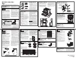
3-Wire Connection: Power Supply Cord

Use this method only if local codes permit connecting chassis 

ground conductor to neutral wire of power supply cord.

1. 

Feed the power supply cord through the strain relief on the 

cord/conduit plate on bottom of range. Allow enough slack 

to easily attach the wiring to the terminal block.

2. 

Use a 3/8" (9.5 mm) nut driver to connect the neutral (white) 

wire to the center terminal block post with one of the 10-32 

hex nuts.

3. 

Connect line 2 (red) and line 1 (black) wires to the outer 

terminal block posts with 10-32 hex nuts.

4. 

Firmly tighten hex nuts.

NOTE:

 For power supply cord replacement, use only a 

power cord rated at 250 volts minimum, 40- or 50-amps 

that is marked for use with nominal 1

3

/

8

" (3.5 cm) diameter 

connection opening, with ring terminals and marked for use 

with ranges.

5. 

Tighten strain relief screws.

IMPORTANT: 

Verify the tightness of the hex nuts.

6. 

Replace lower access cover.

4-Wire Connection: Power Supply Cord

Use this method for:


New branch-circuit installations (1996 NEC)


Mobile homes


Recreational vehicles


In an area where local codes prohibit grounding through the 

neutral

1. 

Cut out and remove part of metal ground strap, as shown.

2. 

Use a Phillips screwdriver to remove the ground-link screw 

from the back of the range. Save the ground-link screw and 

the end of the ground link under the screw.

3. 

Feed the power supply cord through the strain relief on the 

cord/conduit plate on bottom of range. Allow enough slack 

to easily attach the wiring to the terminal block.

A

B

D

C

A.  Terminal block
B.  Ground-link screw
C.  UL Listed strain relief
D.  Power supply cord wires - large opening

A

B

C

D

E

A.  10-32 hex nut
B.  Line 2 (red) wire
C.  Ground-link screw
D.  Neutral (white) wire
E.  Line 1 (black) wire

A

B

C

A  Metal ground strap
B. Discard
C.  Ground-link screw

A

B

D

C

A.  Terminal block
B.  Ground-link screw
C.  UL Listed strain relief
D.  Power supply cord wires

Summary of Contents for YWEE750H0

Page 1: ...IONS D INSTALLATION 23 Déballage de la cuisinière 23 Installation de la bride antibasculement 23 Réglage des pieds de nivellement 24 Réglage de l aplomb de la cuisinière 25 Vérifier que la bride antibasculement est bien installée et engagée 25 Dépose et réinstallation du tiroir 26 Porte du four 26 Achever l installation 27 Índice SEGURIDAD DE LA ESTUFA 28 REQUISITOS DE INSTALACIÓN 29 Herramientas ...

Page 2: ...if range is moved Do not operate range without anti tip bracket installed and engaged Failure to follow these instructions can result in death or serious burns to children and adults Anti Tip Bracket To verify the anti tip bracket is installed and engaged Slide range forward Look for the anti tip bracket securely attached to floor or wall Slide range back so rear range foot is under anti tip brack...

Page 3: ...ty to comply with installation clearances specified on the model serial rating plate The model serial rating plate is located behind the oven door on the top right hand side of the oven frame To eliminate the risk of burns or fire by reaching over the heated surface units cabinet storage space located above the surface units should be avoided If cabinet storage is to be provided the risk can be re...

Page 4: ...g as it conforms to the standards listed above Four wire power supply cord or cable must be used in a mobile home installation Product Dimensions These instructions cover several models Your model may appear different from the models depicted Dimensions given are maximum dimensions across all models Model WEE750H0H IMPORTANT Range must be level after installation Follow the instructions in the Lev...

Page 5: ...et G 131 8 33 3 cm H 711 16 19 5 cm I 413 16 12 2 cm J 311 16 9 4 cm plus measurement of L K Cabinet door or hinges should not extend into the cutout L Remaining counter depth should not exceed 21 4 5 7 cm NOTE 24 61 0 cm minimum when bottom of wood or metal cabinet is shielded by not less than 1 4 6 4 mm flame retardant millboard covered with not less than No 28 MSG sheet steel 0 015 0 4 mm stain...

Page 6: ...connected directly to the circuit breaker box or fused disconnect through flexible or nonmetallic sheathed copper or aluminum cable See the Electrical Connection U S A Only section Allow at least 6 ft 1 8 m of slack in the line so that the range can be moved if servicing is ever necessary A UL Listed conduit connector must be provided at each end of the power supply cable at the range and at the j...

Page 7: ...7 8 12 5 KW 40 or 50 16 6 22 5 KW 12 6 18 5 KW 50 The NEC calculated load is less than the total connected load listed on the model serial rating plate If connecting to a 50 amp circuit use a 50 amp rated cord with kit For 50 amp rated cord kits use kits that specify use with a nominal 13 8 34 9 mm diameter connection opening When a 4 wire single phase 250 volt 60 Hz AC only electrical supply is a...

Page 8: ...cket from the inside of the oven 2 Determine which mounting method to use floor or wall If you have a stone or masonry floor you can use the wall mounting method If you are installing the range in a mobile home you must secure the range to the floor This anti tip bracket and screws can be used with wood or metal studs 3 Determine and mark centerline of the cutout space The mounting bracket can be ...

Page 9: ...counter to the floor 3 Measure the distance from the top of the cooktop to the bottom of the leveling legs This distance should be the same If it is not adjust the leveling legs to the correct height The leveling legs can be loosened to add up to a maximum of 1 2 5 cm A minimum of 3 16 5 mm is needed to engage the anti tip bracket NOTE If height adjustment is made when range is standing tilt the r...

Page 10: ...bottom of the cover toward you and out to remove cover from range 3 Depending on your model remove plastic tag holding three 10 32 hex nuts from the middle post of the terminal block Remove the top 10 32 hex nut from each of the 3 terminal blocks and set aside OR Remove the top 10 32 hex nut from each of the 3 terminal blocks and set aside 4 Assemble a UL Listed strain relief in the opening 5 Comp...

Page 11: ...s IMPORTANT Verify the tightness of the hex nuts 6 Replace lower access cover 4 Wire Connection Power Supply Cord Use this method for New branch circuit installations 1996 NEC Mobile homes Recreational vehicles In an area where local codes prohibit grounding through the neutral 1 Cut out and remove part of metal ground strap as shown 2 Use a Phillips screwdriver to remove the ground link screw fro...

Page 12: ... tightness of the hex nuts 9 Replace lower access cover Install Using Direct Wire Direct Wire Strain Relief 1 Disconnect power 2 Remove the lower access cover screws located on the back of the range Pull the bottom of the cover toward you and out to remove cover from range 3 Depending on your model remove plastic tag holding three 10 32 hex nuts from the middle post of the terminal block Remove th...

Page 13: ...3 Wire Connection Direct Wire 3 7 6 cm 1 0 cm 4 wire direct A circuit breaker box or fused disconnect 4 Wire Connection Direct Wire 12 7 cm 5 1 0 cm 3 Wire Connection Direct Wire Use this method only if local codes permit connecting ground conductor to neutral supply wire 1 Pull the wires through the conduit on cord conduit plate on bottom of range Allow enough slack to easily attach the wiring to...

Page 14: ... 1996 NEC Mobile homes Recreational vehicles In an area where local codes prohibit grounding through the neutral 1 Cut out and remove part of metal ground strap as shown 2 Use a Phillips screwdriver to remove the ground link screw from the back of the range Save the ground link screw and the end of the ground link under the screw 3 Pull the wires through the strain relief on bottom of range Allow ...

Page 15: ...of your foot against the bottom front of the warming drawer or baking drawer to keep the range from moving and then grasp the back of the range as shown 3 Slowly attempt to tilt the range forward If you encounter immediate resistance the range foot is engaged in the anti tip bracket Go to Step 8 4 If the rear of the range lifts more than 1 2 1 3 cm off the floor without resistance stop tilting the...

Page 16: ...For normal range use it is not suggested to remove the oven door However if removal is necessary make sure the oven is off and cool Then follow these instructions The oven door is heavy To Remove 1 Open oven door all the way 2 Pinch the hinge latch between 2 fingers and pull forward Repeat on other side of oven door 3 Close the oven door as far as it will shut 4 Lift the oven door while holding bo...

Page 17: ...lug power cord into a grounded outlet Turn power on 9 Turn on surface burners and oven See the User Guide for specific instructions on range operation NOTE Odors and smoke are normal when the oven is used the first few times If Range Does Not Operate Check the Following Household fuse is intact and tight or circuit breaker has not tripped Range is plugged into a grounded outlet Electrical supply i...

Page 18: ...ANGER ou AVERTISSEMENT Ces mots signifient Risque de basculement Un enfant ou une personne adulte peut faire basculer la cuisinière ce qui peut causer un décès Fixer la bride antibasculement au plancher ou au mur conformément aux instructions d installation Faire glisser de nouveau la cuisinière de façon à ce que le pied arrière de la cuisinière se trouve dans la fente de la bride antibasculement ...

Page 19: ...ilité de respecter les distances de séparation spécifiées sur la plaque signalétique La plaque signalétique se trouve derrière la porte du four dans le coin supérieur droit du châssis Afin de supprimer le risque de brûlures ou d incendie en se penchant au dessus des unités de surface chauffées le rangement en armoire au dessus des unités de surface doit être évité Si des placards de rangement sont...

Page 20: ...ait aux critères des normes mentionnées ci dessus Pour une installation en résidence mobile un câble ou cordon d alimentation à quatre conducteurs doit être utilisé Le câblage de l appareil devra être révisé Dimensions du produit Ces instructions concernent plusieurs modèles Votre modèle peut différer de ceux illustrés Les dimensions indiquées sont les dimensions maximales sur tous les modèles Mod...

Page 21: ... B C D E G H I J F I L A 18 45 7 cm entre le placard latéral supérieur et le plan de travail B 13 33 cm de profondeur maximale du placard supérieur C 30 76 2 cm de largeur min d ouverture D Pour le dégagement minimum par rapport au dessus de la table de cuisson voir la REMARQUE E Largeur min d ouverture 30 76 2 cm F Il est recommandé d effectuer l installation de la canalisation de gaz rigide et d...

Page 22: ...entation et de la protection du circuit 120 240 volts 120 208 volts A 8 8 à 16 5 kW 7 8 à 12 5 kW 40 ou 50 16 6 à 22 5 kW 12 6 à 18 5 kW 50 La charge NEC calculée est inférieure à la charge totale con nectée indiquée sur la plaque signalétique En cas de raccordement à un circuit de 50 A utiliser un cordon de 50 A nominaux avec son nécessaire Pour les ensembles avec cordon de 50 A nominaux utiliser...

Page 23: ...iner la méthode de montage à utiliser au plancher ou au mur Pour un plancher en pierre ou en briquetage on peut utiliser la méthode de montage au mur En cas d installation de la cuisinière dans une résidence mobile il est impératif de fixer la cuisinière au sol Cette bride antibasculement et les vis peuvent servir avec des goujons en métal ou en bois 3 Déterminer et marquer l axe central de l espa...

Page 24: ... et le bas des pieds de nivellement Cette distance doit être la même Dans le cas contraire régler les pieds de nivellement à la hauteur correcte Les pieds de nivellement peuvent être desserrés pour ajouter une hauteur maximale de 1 2 5 cm Une longueur minimale de 3 16 5 mm est nécessaire pour engager la bride antibasculement REMARQUE Si un ajustement de la hauteur est effectué alors que la cuisini...

Page 25: ...ec précaution En cas de résistance immédiate cela signifie que le pied de la cuisinière est engagé dans la bride antibasculement Passer à l étape 8 4 Si l arrière de la cuisinière se soulève de plus de 1 2 1 3 cm du plancher sans opposer de résistance cesser d incliner la cuisinière et la reposer doucement sur le plancher Le pied de la cuisinière n est pas engagé dans la bride antibasculement IMPO...

Page 26: ... une utilisation normale Toutefois si la dépose est nécessaire s assurer que le four est éteint et froid Ensuite suivre les instructions ci dessous La porte du four est lourde Démontage 1 Ouvrir la porte du four complètement 2 Pincer le loquet de charnière entre les deux doigts et le tirer vers l avant Répéter cette opération pour l autre côté de la porte du four 3 Fermer la porte du four aussi lo...

Page 27: ...a terre Mettre l appareil sous tension 9 Mettre en marche les brûleurs de surface et le four Pour des instructions spécifiques concernant l utilisation de la cuisinière consulter le Guide d utilisation REMARQUE Au cours des premières utilisations du four il est normal qu il dégage des odeurs et de la fumée Si la cuisinière ne fonctionne pas contrôler ce qui suit Les fusibles du domicile sont intac...

Page 28: ...jes de seguridad irán a continuación del símbolo de advertencia de seguridad puede morir lesión Peligro de Vuelco Un niño o un adulto puede volcar accidentalmente la estufa y resultar muerto Instale el soporte anti vuelco al piso o a la pared según las instrucciones de instalación Deslice la estufa hacia atrás de modo que la pata trasera quede enganchada en la ranura del soporte anti vuelco Si tra...

Page 29: ...s espacios de instalación especificados en la placa que indica modelo serie valores nominales La placa que indica modelo serie valores nominales está detrás de la puerta del horno en la parte superior del lado derecho del marco del horno Para eliminar el riesgo de quemaduras o incendio al tocar unidades con la superficie demasiado caliente deberá evitarse el uso de armarios de almacenamiento encim...

Page 30: ...istro eléctrico de cuatro hilos Dimensiones del producto Estas instrucciones describen varios modelos la apariencia de su modelo puede diferir de los que se ilustran Las dimensiones que se indican son las dimensiones máximas entre todos los modelos Modelo WEE750H0H IMPORTANTE La estufa debe ser nivelada después de la instalación Siga las instrucciones de la sección Nivelación de la estufa No se re...

Page 31: ...con conexión a tierra G 131 8 33 3 cm H 711 16 19 5 cm I 413 16 12 2 cm J 311 16 9 4 cm más la medición de L K La puerta o las bisagras del armario no deben extenderse dentro del área del recorte L La profundidad de mostrador restante no debe exceder 2 1 4 5 7 cm NOTA 24 61 0 cm como mínimo cuando la base del armario de madera o de metal esté protegida por madera moldeada re tardante de llama de a...

Page 32: ...aja de disyuntores o un desconectador con fusible a través de un cable flexible o con forro no metálico de cobre o aluminio Vea la sección Conexión eléctrica EE UU solamente Deje al menos 6 pies 1 8 m de holgura en la línea para poder mover la estufa si alguna vez se requiere servicio técnico Debe proveerse un conector de conducto homologado por UL en cada extremo del cable de suministro eléctrico...

Page 33: ... del interior del horno 2 Decida qué método de montaje usará en el piso o en la pared Si tiene piso de piedra o de mampostería puede usar el método de montaje en la pared Si instala la estufa en una casa rodante deberá fijar la estufa al piso Este soporte antivuelco y los tornillos se pueden usar con vástagos de madera o de metal 3 Determine y marque la línea central del espacio del recorte El sop...

Page 34: ...o 3 Mida la distancia desde la parte superior de la superficie de cocción hasta la parte inferior de las patas niveladoras La distancia debe ser la misma De lo contrario regule las patas niveladoras para corregir la altura Las patas niveladoras pueden aflojarse para agregar hasta un máximo de 1 2 5 cm Se necesita un mínimo de 3 16 5 mm para enganchar el soporte antivuelco NOTA si regula la altura ...

Page 35: ... tres tuercas hexagonales de 10 32 del poste del medio del bloque de terminales Retire la tuerca hexagonal de 10 32 de la parte superior de cada uno de los 3 bloques de terminales y resérvela O BIEN Retire la tuerca hexagonal de 10 32 de la parte superior cada uno de los 3 bloques de terminales y resérvela 4 Monte un protector de cables aprobado por UL en la abertura 5 Complete la instalación segú...

Page 36: ...onales 6 Vuelva a colocar la cubierta de acceso inferior Conexión de 4 hilos Cable de suministro eléctrico Use este método para Nuevas instalaciones de circuito derivado 1996 NEC Casas rodantes Vehículos de recreación En un área donde los códigos locales prohíban la conexión a tierra a través del terminal neutro 1 Recorte y retire parte de la banda metálica de conexión a tierra como se muestra 2 U...

Page 37: ...e acceso inferior Instalación con un cable directo Protector de cables para cable directo 1 Desconecte el suministro eléctrico 2 Retire los tornillos de la cubierta de acceso inferior en la parte posterior de la estufa Tire de la parte inferior de la cubierta hacia usted y hacia afuera para retirar la cubierta de la estufa 3 Según cuál sea su modelo retire la etiqueta plástica que sostiene tres tu...

Page 38: ... de disyuntores o un desconectador con fusible Conexión de 4 hilos Cable directo 12 7 cm 5 1 0 cm Conexión de 3 hilos Cable directo Use este método solamente si los códigos locales permiten conectar el conductor a tierra al hilo neutro de suministro eléctrico 1 Pase los cables a través del conducto en la placa del cable conducto en la base de la estufa Deje la holgura suficiente como para fijar el...

Page 39: ...creación En un área donde los códigos locales prohíban la conexión a tierra a través del terminal neutro 1 Recorte y retire parte de la banda metálica de conexión a tierra como se muestra 2 Use un destornillador Phillips para retirar el tornillo de enlace a tierra de la parte posterior de la estufa Reserve el tornillo de enlace a tierra y el extremo del enlace a tierra que hay debajo del tornillo ...

Page 40: ...arte posterior de la estufa y la pared posterior 2 Coloque el lado externo del pie contra la parte delantera inferior del cajón de calentamiento o cajón de horneado para impedir que la estufa se mueva después aferre la parte trasera de la estufa como se muestra 3 Intente inclinar lentamente la estufa hacia delante Si enseguida siente resistencia quiere decir que la pata de la estufa está enganchad...

Page 41: ...uerta del horno Sin embargo si es necesario quitarla asegúrese de que el horno esté apagado y frío Después siga estas instrucciones La puerta del horno es pesada Para retirarlo 1 Abra por completo la puerta del horno 2 Tome la traba de la bisagra con 2 dedos y tire hacia adelante Repita en el otro lado de la puerta del horno 3 Cierre la puerta del horno tanto como sea posible 4 Levante la puerta d...

Page 42: ...ra Encienda el aparato 9 Encienda los quemadores de superficie y el horno Vea el Manual del usuario para obtener instrucciones específicas sobre el funcionamiento de la estufa NOTA es normal que haya olores y humo cuando el horno se usa las primeras veces Si la estufa no funciona revise lo siguiente Que el fusible de la casa esté intacto y ajustado o que no se haya disparado el cortacircuitos Que ...

Page 43: ...43 Notas ...

Page 44: ...W11085332A 04 17 2017 All rights reserved Used under license in Canada Tous droits réservés Utilisé sous licence au Canada Todos los derechos reservados Usado en Canadá bajo licencia ...

Reviews: