12
Install Vent System
1.
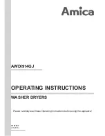
Install exhaust hood
12" min.
(305 mm)
12" min.
(305 mm)
2.
Connect vent to exhaust hood
Install exhaust hood and use caulking compound to seal
exterior wall opening around exhaust hood.
Vent must fit over the exhaust hood. Secure vent to exhaust
hood with 4" (102 mm) clamp. Run vent to dryer location using
straightest path possible. Avoid 90° turns. Use clamps to seal
all joints. Do not use duct tape, screws, or other fastening
devices that extend into interior of vent to secure vent,
because they can catch lint.
The “Vent System Charts” provide venting requirements
that will help achieve best drying performance.
To determine if your model has a long vent system, refer
to the type code located on the serial number plate in the
inner door well. Example: An electric model would be DA
LV
– ELE – XXXXXXX-XXX. A gas model would be DA
LV
– GAS –
XXXXXXX-XXX.
NOTE: For long vent systems, use of box/louvered hoods will
improve venting regardless of length.
Standard Vent System Chart
Number of
90° elbows
Type
of vent
Angled
hoods
0
Rigid metal
64 ft. (20 m)
1
Rigid metal
54 ft. (16.5 m)
2
Rigid metal
44 ft. (13.4 m)
3
Rigid metal
35 ft. (10.7 m)
4
Rigid metal
27 ft. (8.2 m)
Long Vent System Chart
Number of
90° elbows
Type
of vent
Angled
hoods
0
Rigid metal
160 ft. (48.8 m)
1
Rigid metal
150 ft. (45.7 m)
2
Rigid metal
140 ft. (42.7 m)
3
Rigid metal
130 ft. (39.6 m)
4
Rigid metal
120 ft. (36.6 m)
Special provisions for mobile homes:
Exhaust vent must be securely fastened to a noncombustible
portion of mobile home and must not terminate beneath the
mobile home. Terminate exhaust vent outside.
Determine vent path:
■
Select route that will provide straightest and most direct
path outdoors.
■
Plan installation to use fewest number of elbows and turns.
■
When using elbows or making turns, allow as much room
as possible.
■
Bend vent gradually to avoid kinking.
■
Use as few 90° turns as possible.
Determine vent length and elbows needed for best
drying performance:
■
Use the “Vent System Charts” on the next page to determine
type of vent material and hood combinations acceptable
to use.
NOTE: Do not use vent runs longer than those specified
in “Vent System Charts.”
Exhaust systems longer than those specified will:
■
Shorten life of dryer.
■
Reduce performance, resulting in longer drying times
and increased energy usage.
Summary of Contents for WGD7540FW0
Page 2: ...2 DRYER SAFETY ...
Page 3: ...3 ...