background image

TECH SHEET - DO NOT DISCARD

PAGE 7

FOR SERVICE TECHNICIAN’S USE ONLY

PART NO. W10054160

6.

Using figure 8, check for the resistance
values of the motor’s Main and Start
winding coils as shown in the following
table.

NOTE:

Main and Start winding coils

must be checked at the motor.

WINDING

RESISTANCE

CONTACT POINTS

OF MEASUREMENT

MAIN

1.4–2.6

Blue wire in back

at pin 4 and bare

copper wire on pin 5

of black drive motor

switch

START

1.4–2.8

Blue wire in back

at pin 4 and bare

copper wire on pin 3

of black drive motor

switch

If the resistance at the motor is
correct, there is an open circuit
between the motor and machine
control electronics. Check for failed
belt switch.

If the Start winding resistance is
much greater than 4 ohms, replace
the motor.

7.

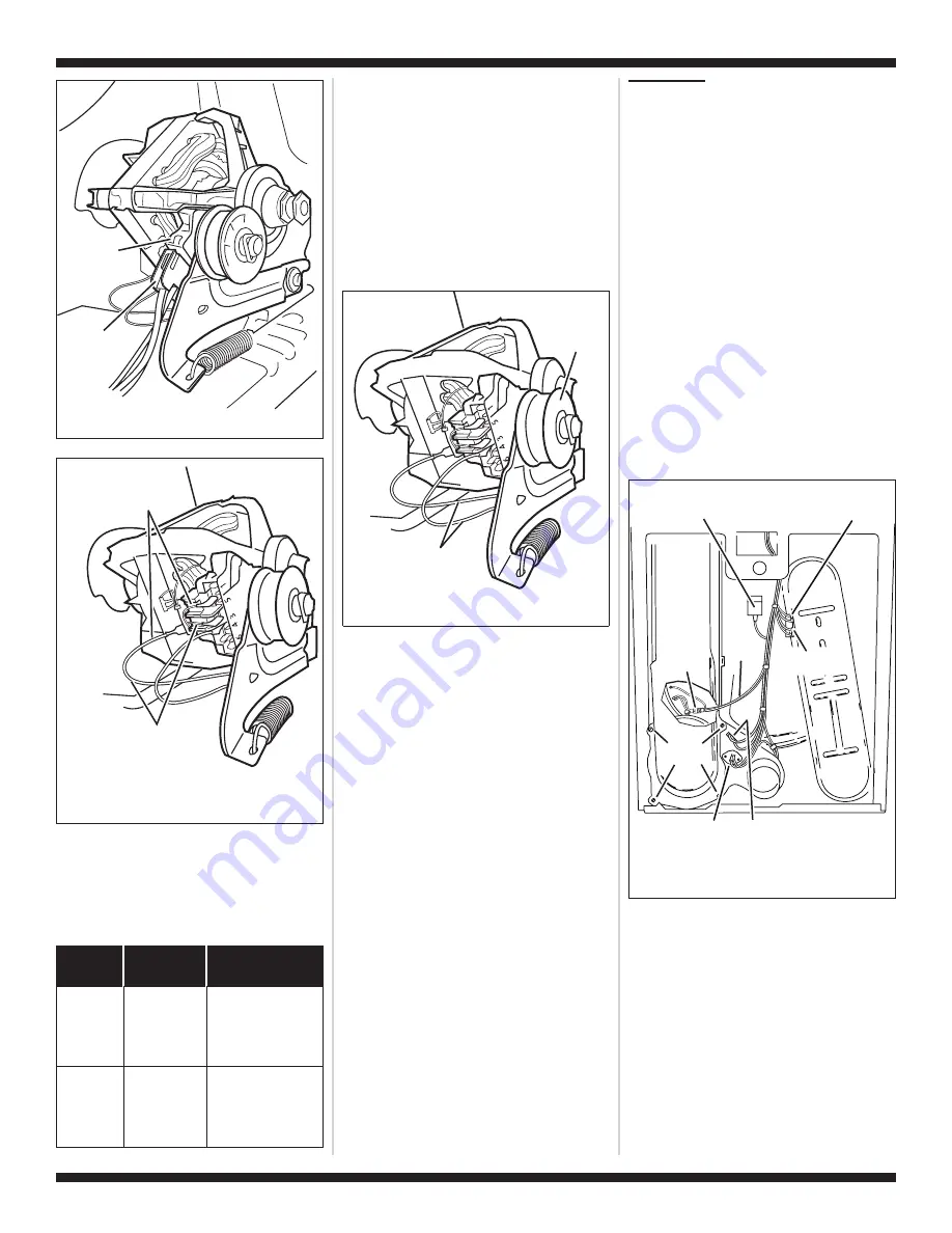
Check the belt switch by measuring
resistance between the two blue wires
as shown in figure 9, while pushing up
the belt switch tension pulley.

If the resistance reading goes from
infinity to a few ohms as pulley arm
closes the switch, belt switch is OK.
If not, replace the belt switch.

If belt switch is OK and there is still
an open circuit, check and repair the
wiring harness.

8.

Door switch problems can be
uncovered in the Door Switch
Diagnostic Test, page 1; however, if this
was not done, the following can be
done without applying power to the
dryer. Connect an ohmmeter across
P8-3 (neutral, white wire) and P8-4
(door, tan wire).

With the door properly closed, the
ohmmeter should indicate a closed
circuit (0–2 ohms).

If not, replace the door switch
assembly. See figure 12, page 10;
and Removing the Front Panel/Drum
Assembly, page 10.

TEST #4

Heater

This test is performed when either of the
following situations occur:

Dryer does not heat

Heat will not shut off

This test checks the components making
up the heating circuit. The following items
are part of this system:

Harness/
connection

Heater relay

High limit
thermostat

Thermal cut-off

Thermal fuse

Gas burner
assembly

Centrifugal switch

Exhaust thermistor

Machine control
electronics. See
ESD information,
page 1.

Gas supply

Dryer does not heat:

Locate the components using figure 2,
page 5; and figure 10.

1.

Unplug dryer or disconnect power.

2.

Remove the back panel to access the
thermal components. See Removing
the Back Panel, page 11.

3.

Perform TEST #4b, page 9. If the
thermal fuse is OK, go to step 4.

4.

Perform TEST #4c, page 9. If the
thermal cut-off is OK, go to step 5.

5.

Locate the high limit thermostat. See
figure 10. Measure the continuity
through it by connecting the meter
probes on the red wire and blue wire
terminals.

Main Winding:

Blue Wire in Back and Bare

Copper Wire (5 Position)

Start Winding:

Blue Wire in Back and Bare

Copper Wire (3 Position)

Figure 8.

Main and start winding

measure points.

Belt Switch

Tension Pulley

Blue Wires

(Back and 4 Position)

Figure 9.

Checking the belt switch.

Drive Motor

Switch

White

Connector

Figure 7.

Remove white connector.

4 Duct
Screws

Thermal

Cut-Off (TCO)

High Limit

Thermostat

Harness

Connection

Thermal

Fuse

Sensor

Wires

Drum
Light

Lint

Duct

Exhaust

Thermistor

Figure 10.

Thermal components,

viewed from rear.

Summary of Contents for WGD6400SW0

Page 1: ...ith all indicators off or with only the Clothes Dry indicator on 2 Select any one button except Pause Cancel and follow the steps below using the same button remember the button Press hold 2 5 seconds Release for 2 5 seconds Press hold 2 5 seconds Release for 2 5 seconds Press hold 2 5 seconds 3 If this test mode has been entered successfully all indicators on the console are illuminated for 5 sec...

Page 2: ...played on the dual 7 segment display A Dryness modifier LED will also be illuminated to indicate the voltage range corresponding to the number displayed The Dryness LEDs relate to specific voltage ranges as follows The More LED will be illuminated for high voltage readings above 132 VAC The Normal LED will be illuminated for normal voltage readings 90 132 VAC The Less LED will be illuminated for l...

Page 3: ... CODES The fault codes below would be indicated when attempting to start a drying cycle or after activating the diagnostic test mode PROBLEM POSSIBLE CAUSE TEST NOTE Possible Cause Tests MUST be performed in the sequence shown for each problem WON T POWER UP No response when buttons are pressed 1 Supply connections See TEST 1 page 6 2 Check harness connections 3 User interface assembly See TEST 6 ...

Page 4: ...2 DATA IN P5 3 VSS P5 4 STROBE P5 6 CLOCK P5 7 BUZZER 12 VDC P1 1 G Y Y R P13 1 P13 2 P14 4 Y R SENSOR G Y SENSOR MOVS Y R BK OUTLET TEMP OUTLET TEMP RTN THERMAL CUT OFF 352 F 178 C MACHINE CONTROL ELECTRONICS USER INTERFACE P8 2 GND W DOOR SWITCH T W P8 4 P8 3 NEUTRAL DOOR NEUTRAL BR BK DRUM LAMP G Y BU P8 1 LAMP LOAD NC NO L1 LINE BK N O COM BK HEATER RELAY P14 3 P14 6 R W R W CENTRIFUGAL SWITCH...

Page 5: ...N P9 2 BK W NEUTRAL N W Y R P13 1 P13 2 Y R SENSOR G Y SENSOR MOVS Y R BK MACHINE CONTROL ELECTRONICS 120 VOLTS MOISTURE SENSOR STRIP CIRCUIT See Removing the Back Panel page 11 to access High Limit Thermostat Thermal Cut off Drum Light Assembly Moisture Sensor Behind Strips Thermal Fuse Exhaust Thermistor See Accessing Removing the Electronic Assemblies page 11 to access Machine Control Electroni...

Page 6: ...ee Accessing Removing the Electronic Assemblies page 11 5 With an ohmmeter check for continuity between the neutral N terminal of the plug and P8 3 white wire on the machine control board The left hand side of figure 5 shows the position of the neutral terminal N on the power cord plug Also see figure 16 page 11 If there is continuity go to step 6 If there is no continuity disconnect the white wir...

Page 7: ...ter should indicate a closed circuit 0 2 ohms If not replace the door switch assembly See figure 12 page 10 and Removing the Front Panel Drum Assembly page 10 TEST 4 Heater This test is performed when either of the following situations occur Dryer does not heat Heat will not shut off This test checks the components making up the heating circuit The following items are part of this system Harness c...

Page 8: ...e heat turn off temperature Medium 140 5 60 3 Low 125 5 52 3 Extra Low 105 5 41 3 The measured overshoot using the glass bulb thermometer in the exhaust outlet can be 30 F 17 C higher 5 If the exhaust temperature is not within specified limits or you have come here from step 3 remove the P14 connector then measure the resistance between P14 3 red white wire and P14 6 red white wire at the connecto...

Page 9: ... If debris is not present replace sensor harness with MOVs Otherwise go to step 7 7 Measure the resistance across each of the outermost contacts and the center terminal ground connection If a resistance less than infinity is measured replace the sensor harness with MOVs 8 If moisture sensor diagnostic test passes check the thermistor Perform TEST 4a page 8 If the problem persists after replacing t...

Page 10: ...d display CF for one second then the current drying mode will be seen on the display The factory default value is 1 2 To select a different drying mode press the Dryness button again The dryer display will flash and show the available settings 3 With the display flashing the selected drying mode press the Start button to save the drying mode and exit the Start button in this mode does not start a ...

Page 11: ...clockwise direction See figure 17 7 Locking tabs located at the bottom of the console insert panel secure the user interface assembly to the console insert panel Using a flat blade screwdriver gently apply pressure to the locking tabs to release the user interface assembly See figure 17 Reinstalling the Electronic Assemblies Refer to preceding removal sections and replace in reverse order NOTE Whe...

Page 12: ...MANUFACTURED UNDER ONE OR MORE OF THE FOLLOWING U S PATENTS 4 669 200 4 700 495 4 754 556 4 840 285 4 865 366 4 899 464 4 908 959 4 989 347 5 066 050 5 560 120 5 809 828 6 020 698 6 047 486 6 199 300 6 446 357 6 597 144 6 604 298 6 685 241 6 732 447 6 784 673 6 819 255 D314 261 D314 262 D457 991 D457 992 D495 453 ...

Reviews: