FOR SERVICE TECHNICIAN’S USE ONLY / POUR LE TECHNICIEN SEULEMENT
IMPORTANT:
Une décharge d’électricité statique peut faire subir des dommages aux circuits électroniques. Pour plus d’informations, se reporter à la fiche technique
du produit en ligne.
Contrôler que la tension est correcte en effectuant les étapes suivantes :
1. Déconnecter la source de courant électrique ou débrancher l’appareil.
2. Brancher le voltmètre au connecteur approprié.
3. Brancher l’appareil
ou reconnecter la source de courant électrique et vérifier la tension.
4. Déconnecter la source de courant électrique ou débrancher l’appareil.
IMPORTANT:
Electrostatic discharge may cause damage to machine control electronics. Refer to online Tech Sheet for additional information.
Check for proper voltage by completing the following steps:
1. Disconnect the power or unplug the appliance.
2. Connect voltage measurement equipment to proper connectors.
3.
Plug in appliance or reconnect power and confirm voltage reading.
4. Disconnect the power or unplug the appliance.
© 2019
W11336173A
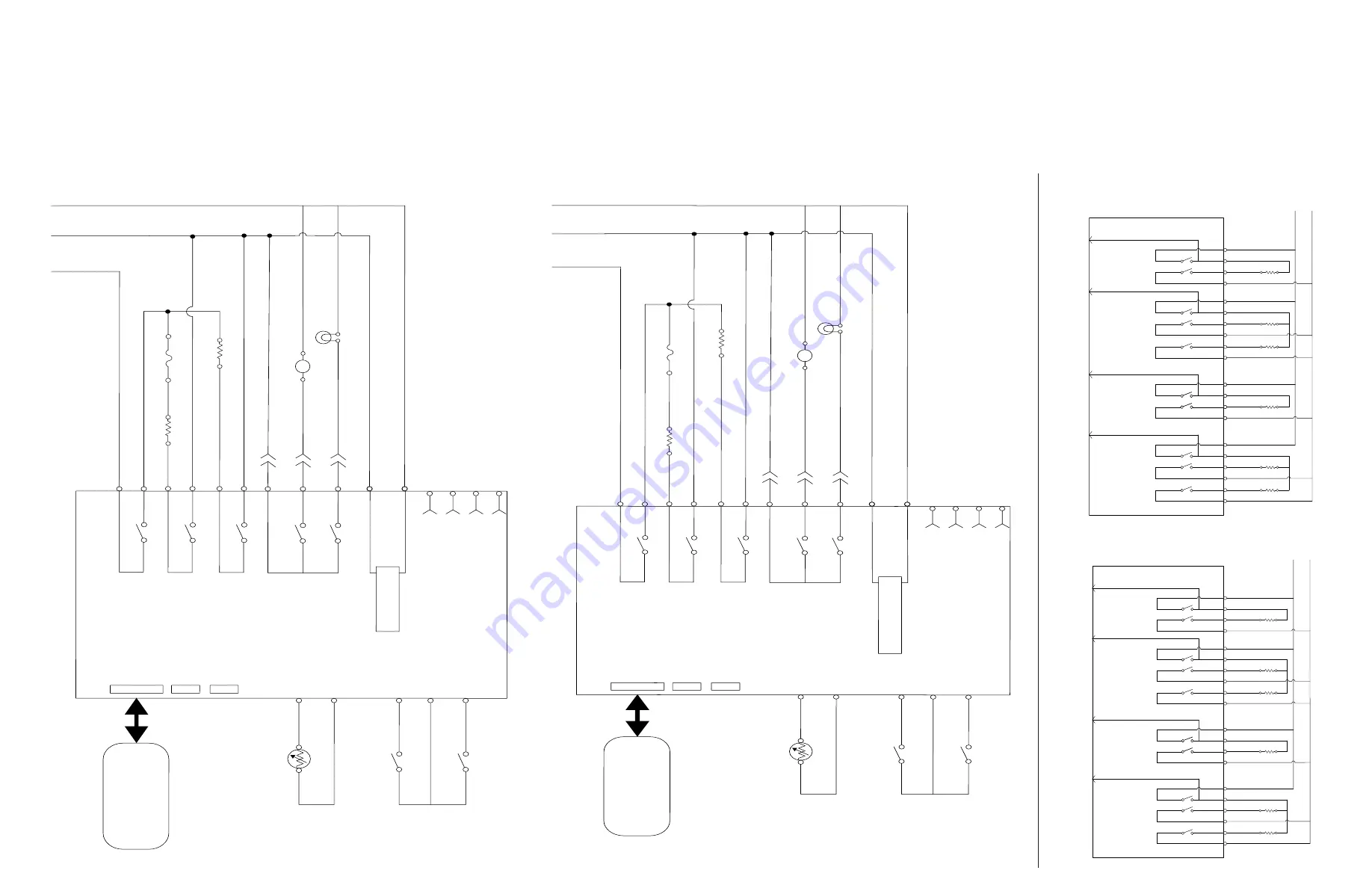
WIRE DIAGRAM / SCHÉMA DE CÂBLAGE
Cooktop
Table de cuisson
1200 W (LR)
RD
YL
YL/BK
BK
BK
P25-3
P25-4
P21-4
P21-7
K9
K8
P10-2
1400 W (LF)
RD
OR
OR/BK
1600W (LF)
V
BK
P24-1
P23-4
P24-4
P24-3
K12
K10
K11
P10-1
1200 W (RR)
RD
BU
BU/BK
BK
P25-3
P25-1
P21-5
P21-7
K14
K13
P10-4
RD
L2
L1
BK
P22-1
P22-2
BK
1400 W (RF)
RD
BR
BR/BK
1600 W (RF)
VT
BK
P23-1
P23-3
P22-4
P22-3
K17
K15
K16
P10-3
P21-3
P21-1
Oven Control LCX 1.5 (Cont.)
1 200 W (ArG)
R
JA
JA/N
N
N
P25-3
P25-4
P21-4
P21-7
K9
K8
P10-2
1 400 W (AvG)
R
OR
OR/N
1 600 W (AvG)
VI
N
P24-1
P23-4
P24-4
P24-3
K12
K10
K11
P10-1
1 200 W (AR)
R
BU
BU/N
N
P25-3
P25-1
P21-5
P21-7
K14
K13
P10-4
R
L2
L1
N
P22-1
P22-2
N
1 400 W (AvD)
R
MAR
MAR/N
1 600 W (AvD)
VI
N
P23-1
P23-3
P22-4
P22-3
K17
K15
K16
P10-3
P21-3
P21-1
Commandes du four LCX 1.5 (Suite)
L2
L1
NeU
Commandes du four LCX 1.5
P2-6
Cuisson au four 2 400 W
Cuisson au gril 3 400 W
Moteur de verrouillage du four
BL
R
N
N
R
Disj. bipol. (P6)
P4-1
P5-4
BU
N
Cuisson au gril (P5)
P5-1
P5-3
Cuisson au four (P4)
P4-3
P4-4
K1
K2
K3
K5
N
N
P2-3
MAR
BL
R
Entrée alimentation (P1)
P1-1
P1-3
N
Alimentation électrique
P3-5
P3-4
Capteur thermométrique du four principal (RTD)
RTD Commune
RTD Four
VI
VI
P3-2
P3-1
Points de test du contacteur
Contacteur
GR
JA
P3-3
Commutateur moteur de verrouillage du four
BU
P11 Clavier
P7 Inutilisé
P9 Inutilisé
Membrane du clavier
P10-4
P10-3
Rétroaction table de cuisson
Lampe four 40 W
K4
P2-1
BL
M
P10-2
P10-1
BU/BL
Fusible thermique
S’ouvre à
363 °F (184 °C)
R
L2
L1
N
Oven Control LCX 1.5
P2-6
Bake 2400 W
Broil 3400 W
Oven Lock Motor
WH
RD
BK
BK
RD
DLB (P6)
P4-1
P5-4
BU
BK
Broil (P5)
P5-1
P5-3
Bake (P4)
P4-3
P4-4
K1
K2
K3
K5
BK
BK
P2-3
BR
WH
RD
Power In (P1)
P1-1
P1-3
BK
Power Supply
P3-5
P3-4
Main Oven Temp Sensor (RTD)
RTD Common
RTD Oven
VT
VT
P3-2
P3-1
Door Position Switch
Switch Common
GY
YL
P3-3
Oven Lock Motor Switch
BU
P11 Keypad
P7 Not Used
P9 Not Used
Membrane Keypad
P10-4
P10-3
Cooktop Feedback
Oven Light 40 W
K4
P2-1
WH
M
P10-2
P10-1
BU/WH
Thermo Fuse
Opens at
363°F (184°C)
RD
Oven
Four


