background image

10

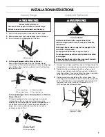
6. Repeat Steps 1 and 2 to ensure that the range foot is 

engaged in the anti-tip bracket.

If the rear of the range lifts more than ½" (1.3 cm) off the floor 
without resistance, the anti-tip bracket may not be installed 
correctly. Do not operate the range without anti-tip bracket 
installed and engaged. Please reference the “Assistance or 
Service” section of the Use and Care Guide, or the cover or 
“Warranty” section of the User Instructions, to contact 
service.

Level Range

Determine if you have AquaLift

®

 Technology or Steam Clean by 

referring to the “Range Care” section of the User Instructions. 

For Ranges with AquaLift

®

 Technology or Steam Clean:

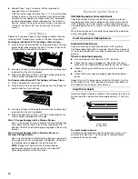
1. Place level on the oven bottom as indicated in one of the two 

figures below depending on the size of the level. Check with 
the level side to side and front to back.

2. If range is not level, pull range forward until rear leveling leg is 

removed from the anti-tip bracket.

3. Follow the directions in Style 1 or Style 2, depending on the 

style of drawer supplied with the range.

For Ranges without AquaLift

®

 Technology or Steam Clean:

1. Place a standard flat rack in oven. 

2. Place level on the rack and check levelness of the range, first 

side to side; then front to back.

3. If range is not level, pull range forward until rear leveling leg is 

removed from the anti-tip bracket. 

4. Follow the directions in Style 1 or Style 2, depending on the 

style of drawer supplied with the range.

Style 1: Ranges Equipped with a Storage Drawer:

Use


a ¼" drive ratchet, wrench or pliers to adjust leveling legs 

up or down until the range is level. Push range back into 
position. Check that rear leveling leg is engaged in the anti-tip 
bracket.

Style 2: Ranges Equipped with a Warming Drawer or 
Premium Storage Drawer:

Use a wrench or pliers to adjust leveling legs up or down until 
the range is level. Push range back into position. Check that 
rear leveling leg is engaged in the anti-tip bracket.

NOTE: Range must be level for satisfactory baking 
performance and best cleaning results using AquaLift

®


Technology and Steam Clean functions.

Electronic Ignition System

Initial lighting and gas flame adjustments

Cooktop and oven burners use electronic igniters in place of 
standing pilots. When the cooktop control knob is turned to the 
“LITE” position, the system creates a spark to light the burner. 
This sparking continues, as long as the control knob is turned to 
“LITE.”

When the oven control is turned to the desired setting, sparking 
occurs and ignites the gas.

Check Operation of Cooktop Burners

Standard Surface Burners

Push in and turn each control knob to the “LITE” position. 

The flame should light within 4 seconds. The first time a burner is 
lit, it may take longer than 4 seconds to light because of air in the 
gas line. 

If burners do not light properly:

Turn cooktop control knob to the “OFF” position. 

Check that the range is plugged in. Check that the circuit 
breaker has not tripped or the household fuse has not blown. 

Check that the gas shutoff valves are set to the “open” 
position. 

Check that burner caps are properly positioned on burner 
bases.

Repeat start-up. If a burner does not light at this point, turn the 
control knobs to the “OFF” position and contact your dealer or 
authorized service company for assistance.

Adjust Flame Height 

Adjust the height of top burner flames. The cooktop “low” burner 
flame should be a steady blue flame approximately ¼" (6.4 mm) 
high.

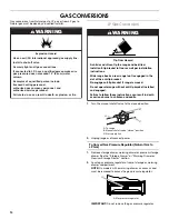
To adjust standard burner:

The flame can be adjusted using the adjustment screw in the 
center of the valve stem. The valve stem is located directly 
underneath the control knob.

A. Low flame
B. High flame

A

B

Summary of Contents for W10658550A

Page 1: ...tallation instructions with the homeowner Homeowner Keep installation instructions for future reference You can be killed or seriously injured if you don t immediately You can be killed or seriously injured if you don t follow All safety messages will tell you what the potential hazard is tell you how to reduce the chance of injury and tell you what can happen if the instructions are not followed ...

Page 2: ...ance This type of ventilation system may cause ignition and combustion problems with this gas cooking appliance resulting in personal injury or unintended operation In the State of Massachusetts the following installation instructions apply Installations and repairs must be performed by a qualified or licensed contractor plumber or gasfitter qualified or licensed by the State of Massachusetts If u...

Page 3: ...e Gas Supply Requirements section Contact a qualified floor covering installer to check that the floor covering can withstand at least 200 F 93 C Use an insulated pad or 6 4 mm plywood under range if installing range over carpeting IMPORTANT To avoid damage to your cabinets check with your builder or cabinet supplier to make sure that the materials used will not discolor delaminate or sustain othe...

Page 4: ...015 0 4 mm stainless steel 0 024 0 6 mm aluminum or 0 020 0 5 mm copper 30 76 2 cm minimum clearance between the top of the cooking platform and the bottom of an uncovered wood or metal cabinet A 27 70 8 cm max depth with handle B 36 91 4 cm cooktop height max with leveling legs screwed all the way in C 46 119 1 cm overall height max with leveling legs screwed all the way in D 29 75 9 cm width E 2...

Page 5: ...ssis of the range is not grounded no keypads will operate Check with a qualified electrician if you are in doubt as to whether the metal chassis of the range is grounded GasSupplyRequirements Observe all governing codes and ordinances IMPORTANT This installation must conform with all local codes and ordinances In the absence of local codes installation must conform with American National Standard ...

Page 6: ...e gas pressure regulator supplied with this range must be used The inlet pressure to the regulator should be as follows for proper operation Natural gas Minimum pressure 5 WCP Maximum pressure 14 WCP LP gas Minimum pressure 11 WCP Maximum pressure 14 WCP Contact local gas supplier if you are not sure about the inlet pressure Burner Input Requirements Input ratings shown on the model serial rating ...

Page 7: ...ave a stone or masonry floor you can use the wall mounting method If you are installing the range in a mobile home you must secure the range to the floor 3 Determine and mark centerline of the cutout space The mounting can be installed on either the left side or right side of the cutout Position mounting bracket against the wall in the cutout so that the V notch of the bracket is 12 31 9 cm from c...

Page 8: ...to the gas shutoff valve Tighten both adapters being certain not to move or turn the gas pressure regulator 3 Use a combination wrench and an adjustable wrench to attach the flexible connector to the adapters IMPORTANT All connections must be wrench tightened Do not make connections to the gas regulator too tight Making the connections too tight may crack the regulator and cause a gas leak Do not ...

Page 9: ...te resistance the range foot is engaged in the anti tip bracket 3 If the rear of the range lifts more than 1 3 cm off the floor without resistance stop tilting the range and lower it gently back to the floor The range foot is not engaged in the anti tip bracket IMPORTANT If there is a snapping or popping sound when lifting the range the range may not be fully engaged in the bracket Check to see if...

Page 10: ...Warming Drawer or Premium Storage Drawer Use a wrench or pliers to adjust leveling legs up or down until the range is level Push range back into position Check that rear leveling leg is engaged in the anti tip bracket NOTE Range must be level for satisfactory baking performance and best cleaning results using AquaLift Technology and Steam Clean functions ElectronicIgnitionSystem Initial lighting a...

Page 11: ...er Flame if needed 1 On models with a warming drawer remove access cover plate 1 screw located at the back of the warming drawer compartment 2 Check the oven bake burner for proper flame This flame should have a 1 3 cm long inner cone of bluish green with an outer mantle of dark blue and should be clean and soft in character No yellow tips blowing or lifting of flame should occur 3 If the oven bak...

Page 12: ...hands pick up the warming drawer or premium storage drawer to complete the removal To Replace 1 Align the forward drawer notches with the notches in the drawer glides on both sides Place the rear alignment tabs into the drawer glides on both sides 2 Push the warming drawer or premium storage drawer in all the way 3 Gently open and close the warming drawer or premium storage drawer to ensure it is ...

Page 13: ... to see which step was skipped 2 Check that you have all of your tools 3 Dispose of recycle all packaging materials 4 Check that the range is level See the Level Range section 5 Use a mild solution of liquid household cleaner and warm water to remove waxy residue caused by shipping material Dry thoroughly with a soft cloth For more information see the Range Care section of the Use and Care Guide o...

Page 14: ...nal approved gas supply line Install a shut off valve Securely tighten all gas connections If connected to LP have a qualified person make sure gas pressure does not exceed 14 36 cm water column Examples of a qualified person include licensed heating personnel authorized gas company personnel and authorized service personnel Failure to do so can result in death explosion or fire A To range B Manua...

Page 15: ... package in the oven Gas orifice spuds are stamped with a number marked with 1 color dot and have a groove in the hex area Replace the Natural gas orifice spud with the correct LP gas orifice spud Refer to the following chart for correct LP gas orifice spud placement LP Gas Orifice Spud Chart for Surface Burners NOTE Refer to the Model Number and Serial Number Plate located on the oven frame behin...

Page 16: ...d turning it clockwise until snug IMPORTANT Do not overtighten 9 Position the back of the bake burner over the oven orifice and slide the tab on front of the bake burner into the front of the oven 10 Reattach the bake burner with 2 screws 11 Insert the tabs on the rear of the flame spreader into the rear of the oven 12 Reattach the front tabs of the flame spreader to the oven with 2 screws 13 Posi...

Page 17: ...have a slightly yellow tip 3 Refer to Complete Installation in the Installation Instructions section of this manual to complete this procedure NOTE Make sure to save the orifices that have just been replaced in the conversion NaturalGasConversion 1 Turn the manual shutoff valve to the closed position 2 Unplug range or disconnect power To Convert Gas Pressure Regulator LP Gas to Natural Gas 1 Remov...

Page 18: ...pud Chart NOTE Refer to the Model Number and Serial Number Plate located on the oven frame behind the top left side of the oven door for proper sizing of spuds for each burner location 5 Place LP gas orifice spuds in plastic parts bag for future use and keep with package containing literature 6 Replace the burner base using both screws 7 Replace burner cap 8 Repeat steps 1 7 for the remaining burn...

Page 19: ...bake burner with 2 screws 11 Insert the tabs on the rear of the flame spreader into the rear of the oven 12 Reattach the front tabs of the flame spreader to the oven with 2 screws 13 Position the front of the oven bottom panel toward the front frame and lower the rear of the oven bottom panel into the oven 14 Reattach the oven bottom panel with 2 screws To Convert Oven Broil Burner LP Gas to Natur...

Page 20: ...ral Gas 1 Refer to the Make Gas Connection section for properly connecting the range to the gas supply 2 Refer to the Electronic Ignition System section for proper burner ignition operation and burner flame adjustments IMPORTANT You may have to adjust the LO setting for each cooktop burner Checking for proper cooktop bake and broil burner flame is very important Natural gas flames do not have yell...

Reviews: