background image

5

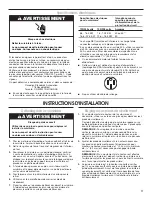
Electrical Requirements - Canada Only

If codes permit and a separate ground wire is used, it is 

recommended that a qualified electrical installer determine that 

the ground path is adequate and wire gauge are in accordance 

with local codes.
Be sure that the electrical connection and wire size are adequate 

and in conformance with CSA Standard C22.1, Canadian 

Electrical Code, Part 1 - latest edition, and all local codes and 

ordinances.
A copy of the above code standards can be obtained from:

Canadian Standards Association 

178 Rexdale Blvd. 

Toronto, ON M9W 1R3 CANADA


Check with a qualified electrical installer if you are not sure 

the range is properly grounded.

 * The NEC calculated load is less than the total connected load 

listed on the model/serial/rating plate.

 ** If connecting to a 50-amp circuit, use a 50-amp rated cord 

with kit. For 50-amp rated cord kits, use kits that specify use 

with a nominal 1

3

/

8

" (34.9 mm) diameter connection opening.


A time-delay fuse or circuit breaker is recommended.


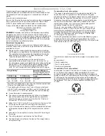
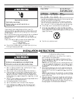
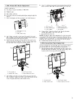
This range is equipped with a CSA International Certified 

Power Cord intended to be plugged into a standard 14-50R 

wall receptacle. Be sure the wall receptacle is within reach of 

range’s final location.


Do not use an extension cord.

WARNING

Electrical Shock Hazard

Electrically ground range.
Failure to do so can result in death, fire, or 

electrical shock.

Range Rating*

Specified Rating of 

Power Supply Cord Kit 

and Circuit Protection

120/240 Volts

120/208 Volts

Amps

8.8 - 16.5 KW
16.6 - 22.5 KW

7.8 - 12.5 KW
12.6 - 18.5 KW

40 or 50**
50

INSTALLATION INSTRUCTIONS

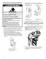
Unpack Range

1. 

Remove shipping materials, tape, and film from the range. 

Keep cardboard bottom under range.

2. 

Remove oven racks and parts package from inside oven.

3. 

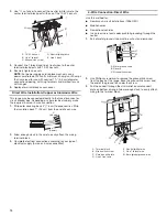
To place range on its back, take 4 cardboard corners from 

the carton. Stack one cardboard corner on top of another. 

Repeat with the other 2 corners. Place them lengthwise on 

the floor behind the range to support the range when it is laid 

on its back.

4. 

Using 2 or more people, firmly grasp the range and gently lay 

it on its back on the cardboard corners.

5. 

Pull cardboard bottom firmly to remove.

6. 

Use an adjustable wrench to loosen the leveling legs.

7. 

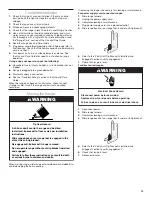
Place cardboard or hardboard in front of range. Using 2 

or more people, stand range back up onto cardboard or 

hardboard.

Adjust Leveling Legs

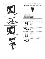
1. 

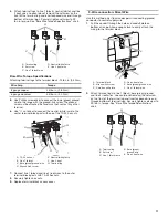
If range height adjustment is necessary, use a wrench or 

pliers to loosen the 4 leveling legs.
This may be done with the range on its back or with the 

range supported on 2 legs after the range has been placed 

back to a standing position.

NOTE:

 To place range back up into a standing position, put 

a sheet of cardboard or hardboard in front of range. Using 2 

or more people, stand range back up onto the cardboard or 

hardboard.

2. 

Adjust the leveling legs to the correct height. Leveling legs 

can be loosened to add up to a maximum of 1" (2.5 cm). A 

minimum of 

3

/

16

" (5.0 mm) is needed to engage the anti-tip 

bracket.

NOTE:

 If height adjustment is made when range is standing, 

tilt the range back to adjust the front legs, then tilt forward to 

adjust the rear legs.

3. 

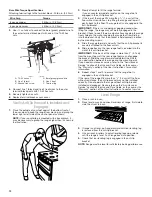
When the range is at the correct height, check that there is 

adequate clearance under the range for the anti-tip bracket. 

Before sliding range into its final location, check that the 

anti-tip bracket will slide under the range and onto the rear 

leveling leg prior to anti-tip bracket installation.

WARNING

Excessive Weight Hazard

Use two or more people to move and install range.
Failure to do so can result in back or other injury.

Summary of Contents for W10430958A

Page 1: ...en installée et engagée 18 Réglage de l aplomb de la cuisinière 19 Achever l installation 20 Déplacement de la cuisinière 20 Table of Contents Table des matières W10575959B IMPORTANT Save for local electrical inspector s use IMPORTANT À conserver pour consultation par l inspecteur local des installations électriques RANGE SAFETY You can be killed or seriously injured if you don t immediately You c...

Page 2: ...at are shown must be used Given dimensions are minimum clearances The floor anti tip bracket must be installed To install the antitip bracket shipped with the range see the Install Anti Tip Bracket section Grounded electrical supply is required See the Electrical Requirements section IMPORTANT To avoid damage to your cabinets check with your builder or cabinet supplier to make sure that the materi...

Page 3: ...imum when bottom of wood or metal cabinet is covered by not less than 1 4 0 64 cm flame retardant millboard covered with not less than No 28 MSG sheet steel 0 015 0 4 mm stainless steel 0 024 0 6 mm aluminum or 0 020 0 5 mm copper 30 76 2 cm minimum clearance between the top of the cooking platform and the bottom of an uncovered wood or metal cabinet A 353 4 1 8 90 8 cm 0 3 cm cooktop height minim...

Page 4: ... aluminum cable See the Electrical Connection U S A Only section Allow 2 to 3 ft 61 0 cm to 91 4 cm of slack in the line so that the range can be moved if servicing is ever necessary A UL Listed conduit connector must be provided at each end of the power supply cable at the range and at the junction box Wire sizes and connections must conform with the rating of the range The wiring diagram is loca...

Page 5: ...nder range 2 Remove oven racks and parts package from inside oven 3 To place range on its back take 4 cardboard corners from the carton Stack one cardboard corner on top of another Repeat with the other 2 corners Place them lengthwise on the floor behind the range to support the range when it is laid on its back 4 Using 2 or more people firmly grasp the range and gently lay it on its back on the c...

Page 6: ...ket holes of the determined mounting method See the following illustrations 5 Using a Phillips screwdriver mount anti tip bracket to the wall or floor with the two 12 x 15 8 screws provided WARNING Tip Over Hazard A child or adult can tip the range and be killed Install anti tip bracket to floor or wall per installation instructions Slide range back so rear range foot is engaged in the slot of the...

Page 7: ...cord through the strain relief in the cord conduit plate on bottom of range Allow enough slack to easily attach the wiring to the terminal block Tighten strain relief screw against the power supply cord WARNING Electrical Shock Hazard Disconnect power before servicing Use a new 40 amp power supply cord Plug into a grounded outlet Failure to follow these instructions can result in death fire or ele...

Page 8: ...nstallation following instructions for your type of electrical connection 4 wire recommended 3 wire if 4 wire is not available Electrical Connection Options If your home has And you will be connecting to Go to Section 4 wire receptacle NEMA type 14 50R A UL Listed 250 volt minimum 40 amp range power supply cord 4 Wire Connection Power Supply Cord 4 wire direct A fused disconnect or circuit breaker...

Page 9: ...6 Connect line 1 black and line 2 red wires to the outer terminal block posts with 10 32 hex nuts 7 Securely tighten hex nuts NOTE For power supply cord replacement only use a power cord rated at 250 volts minimum 40 amps or 50 amps that is marked for use with nominal 13 8 3 5 cm diameter connection opening with ring terminals and marked for use with ranges 8 Replace terminal block access cover 3 ...

Page 10: ...nough slack in the wire to easily attach the wiring terminal block 3 Complete electrical connection according to your type of electrical supply 4 wire or 3 wire connection 4 Wire Connection Direct Wire Use this method for New branch circuit installations 1996 NEC Mobile homes Recreational vehicles In an area where local codes prohibit grounding through the neutral 1 Part of metal ground strap must...

Page 11: ...ely tighten hex nuts 9 Replace terminal block access cover 3 Wire connection Direct Wire Use this method only if local codes permit connecting ground conductor to neutral supply wire 1 Pull the conduit through the hole and conduit plate on bottom of range Allow enough slack to easily attach the wiring to the terminal block 2 Attach terminal lugs to line 1 black bare green ground and line 2 red wir...

Page 12: ...he mounting screws 4 Slide the range forward and verify that the anti tip bracket is securely attached to the floor or wall 5 Slide range back so the rear range foot is inserted into the slot of the anti tip bracket IMPORTANT If the back of the range is more than 2 5 1 cm from the mounting wall the rear range foot may not engage the bracket Slide the range forward and determine if there is an obst...

Page 13: ...g range slide range onto cardboard or hardboard to avoid damaging the floor covering If removing the range is necessary for cleaning or maintenance For power supply cord connected ranges 1 Slide range forward 2 Unplug the power supply cord 3 Complete cleaning or maintenance 4 Plug power supply cord into a grounded outlet 5 Slide range back so rear range foot is under anti tip bracket 6 Refer to th...

Page 14: ...ANGER ou AVERTISSEMENT Ces mots signifient Risque de basculement Un enfant ou une personne adulte peut faire basculer la cuisinière ce qui peut causer un décès Fixer la bride antibasculement au plancher ou au mur conformément aux instructions d installation Faire glisser de nouveau la cuisinière de façon à ce que le pied arrière de la cuisinière se trouve dans la fente de la bride antibasculement ...

Page 15: ... se pencher au dessus des plaques de cuisson chaudes les placards de rangement au dessus des plaques doivent être évités Si des placards de rangement sont envisagés le risque peut être réduit par l installation d une hotte de cuisine dépassant le bas des placards d au moins 5 12 7 cm horizontalement Respecter les dimensions indiquées pour les ouvertures à découper dans les placards Ces dimensions ...

Page 16: ...UE Distance de séparation minimale de 24 61 cm lorsque le fond d un placard de bois ou de métal est protégé par une planche ignifugée d au moins 1 4 0 64 cm recouverte d une feuille métallique d épaisseur égale ou supérieure à acier calibre 28 MSG acier inoxydable 0 015 0 4 mm aluminium 0 024 0 6 mm ou cuivre 0 020 0 5 mm Distance de séparation de 30 76 2 cm ou plus entre le dessus de la table de ...

Page 17: ...ière la cuisinière en guise de support lorsque la cuisinière est placée sur sa partie postérieure 4 À l aide de deux personnes ou plus saisir fermement la cuisinière et la poser délicatement sur sa partie postérieure sur les coins de protection 5 Tirer fermement sur la partie inférieure du carton pour le retirer 6 Utiliser une clé à molette pour desserrer les pieds de nivellement 7 Placer le carto...

Page 18: ...du four et saisir le côté inférieur droit ou gauche du tableau de commande tel qu indiqué REMARQUE Si le plan de travail comporte un dosseret il faudra peut être saisir la cuisinière plus haut que ce qu indique l illustration 2 Tenter d incliner la cuisinière vers l avant avec précaution Si vous rencontrez une résistance immédiate cela signifie que le pied de la cuisinière est engagé dans la bride...

Page 19: ... du guide d utilisation et d entretien la couverture ou la section Garantie des instructions d utilisation pour obtenir les coordonnées des personnes à contacter 6 Répéter les étapes 1 et 2 pour s assurer que le pied de la cuisinière est bien engagé dans la bride antibasculement Si l arrière de la cuisinière se soulève de plus de 1 2 1 3 cm du plancher sans opposer de résistance cela peut signifie...

Page 20: ...est correctement alimentée Consulter la section Dépannage dans le Guide d utilisation et d entretien Après 5 minutes de fonctionnement de la cuisinière vérifier la chaleur Si la cuisinière est froide l éteindre et contacter un technicien qualifié Déplacement de la cuisinière Lorsqu on déplace la cuisinière la faire glisser sur une planche de carton ou en matériau dur pour éviter d endommager le re...

Reviews: