background image

6

Electrical Requirements

Observe all governing codes and ordinances.

Required:


A 120 V, 60 Hz, AC only, 15 or 20 A electrical supply with a 

fuse or circuit breaker

Recommended:


A time-delay fuse or time-delay circuit breaker


A separate circuit serving only this microwave oven

Electrical Shock Hazard

Plug into a grounded 3 prong outlet.
Do not remove ground prong.
Do not use an adapter.
Do not use an extension cord.
Failure to follow these instructions can result in death, 
fire, or electrical shock.

WARNING

GROUNDING INSTRUCTIONS

SAVE THESE INSTRUCTIONS

For all cord connected appliances:

The microwave oven must be grounded. In the event of

an electrical short circuit, grounding reduces the risk of

electric shock by providing an escape wire for the electric

current. The microwave oven is equipped with a cord

having a grounding wire with a grounding plug. The plug

must be plugged into an outlet that is properly installed

and grounded.

WARNING:


Improper use of the grounding plug can

result in a risk of electric shock. Consult a qualified 

electrician or serviceman if the grounding instructions are 

not completely understood, or if doubt exists as to whether 

the microwave oven is properly grounded. 
Do not use an extension cord. If the power supply cord is 

too short, have a qualified electrician or serviceman install 

an outlet near the microwave oven.

This device complies with Part 18 of the FCC Rules.

Summary of Contents for KMBT5011K

Page 1: ...o use como horno de microondas para mostrador Table of Contents Índice MICROWAVE OVEN SAFETY W11412752C MICROWAVE OVEN SAFETY 1 INSTALLATION REQUIREMENTS 2 Tools and Parts 2 Location Requirements 3 Product Dimensions 4 Required Cutout Dimensions 5 Electrical Requirements 6 INSTALLATION INSTRUCTIONS 7 Unpacking Instructions 7 Prepare Microwave Oven 7 Install the Rails 8 Install the Microwave Oven 9...

Page 2: ... screw 2 extra 7 16x7 16 round head wood screw 4 extra Parts Supplied not shown to scale This installation instruction is for various models Some parts supplied may have different appearance depending on your model NOTE Trim kit frame 1 Cooling Ducts 2 and Rail 2 parts will need to be purchased to convert from Standard to Slim or from a Slim to a Standard installation Parts supplied for model WMT5...

Page 3: ... oven 1 Minimum distance of 36 91 4 cm from the floor to the cutout floor 2 The microwave oven may also be installed in a cabinet by itself without a built in oven below Allow a clearance of at least 19 16 4 0 cm below the cabinet 3 Make sure the surrounding cabinetry has clearance to open and close freely Allow a clearance of at least 2 5 1 cm above the cutout opening Installed over a built in ov...

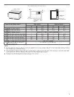
Page 4: ... C Depth of unit 18 45 7 18 45 7 D Height of unit without trim kit frame 105 16 26 2 105 16 26 2 E Width of unit without trim kit frame 2713 16 70 7 2713 16 70 7 F Trim kit frame thickness visible 7 8 2 2 7 8 2 2 G Total thickness of frame 25 16 5 8 25 16 5 8 H Trim kit frame inner opening width 28 71 1 28 71 1 J Trim kit frame inner opening height 109 16 26 9 109 16 26 9 D E B A C F G H J ...

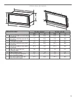
Page 5: ...ended region for receptacle Upper right quadrant J Receptacle surface to the back of the microwave oven 4 10 2 cm J 40 102 cm NOTE Flush receptacle is recommended For non flush receptacle make sure you have at least 4 10 2 cm clearance between the back of microwave oven and the receptacle If the receptacle is placed outside of the recommended region make sure from the back of the microwave oven to ...

Page 6: ...oven must be grounded In the event of an electrical short circuit grounding reduces the risk of electric shock by providing an escape wire for the electric current The microwave oven is equipped with a cord having a grounding wire with a grounding plug The plug must be plugged into an outlet that is properly installed and grounded WARNING Improper use of the grounding plug can result in a risk of ...

Page 7: ...on Insert the four trim kit frame locating holes to the four microwave oven locating pins Install the trim kit frame in the proper orientation TOP side is marked Secure the trim kit frame to the microwave oven using four 7 18x7 16 round head sheet metal screws 4 Secure the two cooling ducts to the top of the microwave oven using six 7 18x7 16 round head sheet metal screws NOTE The cooling duct may...

Page 8: ...the cabinet lower front wall and two screw pilot holes E and H inside the bottom of cabinet 5 Put the two rails inside the cabinet and align the screw holes on rails and pilot holes on cabinet 6 Attach the two rails using the six 7 16x7 16 round head wood screws A Cabinet B Rails C Side wall A 20 52 7 cm B C A Cabinet B Rails C Hole C on left rail D Hole D on left rail E Hole E on left rail F Hole...

Page 9: ...ot overtighten screws Installation is now complete Replace any loose items that have been removed from microwave oven cavity Save these Installation Instructions for future reference Install the Microwave Oven 1 Position microwave oven near cutout opening 2 Plug in microwave oven 3 Slide the microwave oven back and into place 4 Adjust the microwave oven gently to the cutout cabinet center Electric...

Page 10: ...nstrucciones Su seguridad y la seguridad de los demás es muy importante Hemos incluido muchos mensajes importantes de seguridad en este manual y en su electrodoméstico Lea y obedezca siempre todos los mensajes de seguridad ADVERTENCIA PELIGRO Este es el símbolo de alerta de seguridad Este símbolo le llama la atención sobre peligros potenciales que pueden ocasionar la muerte o una lesión a usted y ...

Page 11: ...edonda para madera n 7 16 x 7 16 4 adicionales Piezas suministradas no se muestran a escala Estas instrucciones de instalación son para varios modelos Algunas piezas suministradas pueden tener una apariencia diferente según su modelo NOTA Las piezas del marco del kit de molduras 1 los conductos de enfriamiento 2 y la guía 2 deberán comprarse para convertir la instalación del producto de estándar a...

Page 12: ... 91 4 cm desde el piso hasta la base de recorte 2 El horno de microondas también se puede instalar solo en un gabinete sin un horno integrado debajo Deje un espacio libre de al menos 19 16 4 0 cm debajo del gabinete 3 Cerciórese de que haya espacio suficiente para que los gabinetes que están alrededor puedan abrirse y cerrarse libremente Deje un espacio libre de al menos 2 5 1 cm por encima de la ...

Page 13: ...idad 18 45 7 18 45 7 D Altura de la unidad sin marco del kit de molduras 105 16 26 2 105 16 26 2 E Ancho de la unidad sin marco del kit de molduras 2713 16 70 7 2713 16 70 7 F Espesor del marco del kit de molduras visible 7 8 2 2 7 8 2 2 G Espesor total del marco 25 16 5 8 25 16 5 8 H Ancho de la apertura interior del marco del kit de molduras 28 71 1 28 71 1 J Altura de la apertura interior del m...

Page 14: ...eceptáculo Cuadrante superior derecho J De la superficie del receptáculo a la parte posterior del horno de microondas 4 10 2 cm J 40 102 cm NOTA Se recomienda receptáculo al ras Para receptáculos que no estén al ras asegúrese de tener un espacio libre de al menos 4 10 2 cm entre la parte posterior del horno de microondas y el receptáculo Si el receptáculo se coloca fuera de la región recomendada a...

Page 15: ...nectado a tierra En caso de que se produzca un cortocircuito la conexión a tierra reduce el riesgo de electrocución por medio de un alambre de escape para la corriente eléctrica El horno de microondas está equipado con un cable que tiene un alambre de conexión a tierra con un enchufe para conexión a tierra El enchufe debe estar conectado a un tomacorriente que está correctamente instalado y conect...

Page 16: ...o del kit de molduras en los cuatro pasadores de ubicación del horno de microondas Instale el marco del kit de molduras en la orientación adecuada El lado TOP Superior está marcado Fije el marco del kit de molduras al horno de microondas con cuatro tornillos de cabeza redonda para chapa n 7 18 x 7 16 4 Asegure los dos conductos de enfriamiento a la parte superior del horno de microondas con seis t...

Page 17: ...inete y dos orificios piloto E y H dentro de la parte inferior del gabinete 5 Coloque las dos guías dentro del gabinete y alinee los orificios de los tornillos en las guías con los orificios piloto en el gabinete 6 Fije las dos guías con los seis tornillos de cabeza redonda para madera n 7 16 x 7 16 A Gabinete B Guías C Pared lateral A 20 52 7 cm B C A Gabinete B Guías C Orificio C en la guía izqu...

Page 18: ...mpletado la instalación Vuelva a colocar los artículos sueltos que se quitaron de la cavidad del horno de microondas Conserve estas instrucciones de instalación para referencia futura Instalación del horno de microondas 1 Coloque el horno de microondas cerca de la abertura del recorte 2 Enchufe el horno de microondas 3 Deslice el horno de microondas hacia atrás hasta que llegue a su lugar 4 Ajuste...

Page 19: ...19 NOTAS ...

Page 20: ...NOTAS W11412752C 2020 All rights reserved Todos los derechos reservados 06 20 ...

Reviews: