background image

8

GB

!

 Before operating the product, remove all plastic

film from the sides of the appliance.

Using the hob

Lighting the burners

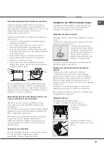
For each BURNER knob there is a complete ring
showing the strength of the flame for the relevant
burner.
To light one of the burners on the hob:
1. Bring a flame or gas lighter close to the burner.
2. Press the BURNER knob and turn it in an
anticlockwise direction so that it is pointing to the
maximum flame setting 

E

.

3. Adjust the intensity of the flame to the desired
level by turning the BURNER knob in an
anticlockwise direction. This may be the minimum
setting 

C

, the maximum setting 

E

 or any position in

between the two.
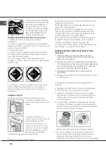
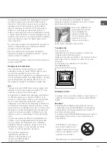
If the appliance is fitted
with an electronic lighting
device* (

see figure; C),

press the BURNER knob
and turn it in an
anticlockwise direction,
towards the minimum
flame setting, until the
burner is lit. The burner

may be extinguished when the knob is released. If this
occurs, repeat the operation, holding the knob down
for a longer period of time.

!

 Since the hob burners are equipped with a safety

device (X), you must hold the control knob in for
about 3-7 seconds after the burner has been lighted
to allow the gas to pass until the safety
thermocouple has heated.

!

 If the flame is accidentally extinguished, switch off

the burner and wait for at least 1 minute before
attempting to relight it.

To switch the burner off, turn the knob until it
reaches the stop position 

•.

Practical advice on using the burners

For the burners to work in the most efficient way
possible and to save on the amount of gas
consumed, it is recommended that only pans that
have a lid and a flat base are used. They should also
be suited to the size of the burner.

Start-up and use

To identify the type of burner, please refer to the
diagrams contained in the “Burner and nozzle
specifications”.

!

 On the models supplied with a reducer shelf,

remember that this should be used only for the
auxiliary burner when you use casserole dishes with
a diameter under 12 cm.

Using the oven

!

 The first time you use your appliance, heat the

empty oven with its door closed at its maximum
temperature for at least half an hour. Ensure that the
room is well ventilated before switching the oven off
and opening the oven door. The appliance may emit
a slightly unpleasant odour caused by protective
substances used during the manufacturing process
burning away.

!

 Never put objects directly on the bottom of the

oven; this will avoid the enamel coating being
damaged. Only use position 1 in the oven when
cooking with the rotisserie spit.

.

*

 Only available in certain models

Burner

ø Cookware diameter (cm)

Fast (R)

24 - 26

Semi Fast (S)

16 - 20

Auxiliary (A)

10 - 14

X

C

Flame adjustment according to levels

the burner flame intensity can be adjusted with the 
knob according to 6 power levels, from maximum
to  minimum with 4 intermediate positions:

a click will indicate the change from one level to 
another when turning the knob. The system 
guarantees a more precise adjustment, allows
 to replicate the flame intensity and to identify 
easily the preferred level for different cooking 
operations.

Flame adjustment according to levels

Flame adjustment according to levels

WARNING! The glass lid can break 

in if it is heated up. Turn off all the 

burners and the electric plates be-

fore closing the lid.*


Summary of Contents for H6GG1E FR

Page 1: ...l Start up and use 8 Using the hob Using the oven Oven cooking advice table Precautions and tips 11 General safety Disposal Respecting and conserving the environment Care and maintenance 12 Switching the appliance off Cleaning the appliance Replacing the oven light bulb Gas tap maintenance The catalytic self cleaning system Assistance Operating Instructions GB FR H6TGC1E FR H6GG1E FR H6TGC1E FR H6...

Page 2: ...ombustion fumes should be guaranteed using a hood connected to a safe and efficient natural suction chimney or using an electric fan that begins to operate automatically every time the appliance is switched on see figure Installation A After prolonged use of the appliance it is advisable to open a window or increase the speed of any fans used The liquefied petroleum gases are heavier than air and ...

Page 3: ...l socket must be easily accessible The cable must not be bent or compressed The cable must be checked regularly and replaced by authorised technicians only The manufacturer declines any liability should these safety measures not be observed Gas connection Connection to the gas network or to the gas cylinder may be carried out using a flexible rubber or steel hose in accordance with current nationa...

Page 4: ...the burners off their seats 2 Unscrew the nozzles using a 7 mm socket spanner see figure and replace them with nozzles suited to the new type of gas see Burner and nozzle specifications table 3 Replace all the components by following the above instructions in reverse Adjusting the hob burners minimum setting 1 Turn the tap to the minimum position 2 Remove the knob and adjust the regulatory screw w...

Page 5: ...see pictures 2 Unscrew the nozzles using a 7 mm socket spanner Replace the nozzles with models that are configured for use with the new type of gas see Table 1 The two nozzles have the same hole diameter 3 Replace all the components by completing the above operations in reverse order Adjusting the burners primary air small but steady 3 Having adjusted the flame to the required low setting while th...

Page 6: ...e P C S 50 37 MJ Kg Natural P C S 37 78 MJ m TECHNICAL DATA Oven Dimensions HxWxD 31x43 5x43 5 cm Volume 58 l Useful measurements relating to the oven compartment width 46 cm depth 42 cm height 8 5 cm Voltage and frequency see data plate Burners may be adapted for use with any type of gas shown on the data plate EC Directives 2006 95 EC dated 12 12 06 Low Voltage and subsequent amendments 04 108 E...

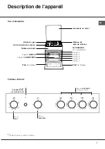
Page 7: ...id Glass cover Control panel GRILL rack DRIPPING PAN GUIDE RAILS for the sliding racks position 3 position 2 position 1 Gas burner Containment surface for spills Adjustable foot Adjustable foot position 5 position 4 OVEN control knob TIMER knob Hob BURNER control knobs OVEN LIGHT and ROTISSERIE button ...

Page 8: ... of gas consumed it is recommended that only pans that have a lid and a flat base are used They should also be suited to the size of the burner Start up and use To identify the type of burner please refer to the diagrams contained in the Burner and nozzle specifications On the models supplied with a reducer shelf remember that this should be used only for the auxiliary burner when you use casserol...

Page 9: ...l When using the grill leave the oven door ajar positioning the deflector D between the door and the control panel see figure in order to prevent the knobs from overheating Turnspit To operate the rotisserie see diagram proceed as follows 1 Place the dripping pan in position 1 2 Place the rotisserie support in position 4 and insert the spit in the hole provided on the back panel of the oven 3 Acit...

Page 10: ...scuits Tart Savoury pies Leavened cakes 0 5 1 1 1 1 3 3 3 3 15 15 15 15 180 180 180 180 30 35 30 35 45 50 35 40 Grilled foods Veal steak Cutlets Hamburgers Mackerel Toast 1 1 5 1 1 4 pcs 4 4 3 4 4 5 5 5 5 5 15 20 20 20 30 15 20 2 4 Grilling using the rotisserie Spit roast veal Spit roast chicken 1 2 5 5 70 80 70 80 Grilling using the multi spit rotisserie Meat kebabs Vegetable kebabs 1 0 8 5 5 40 ...

Page 11: ...y mains If the appliance breaks down under no circumstances should you attempt to repair the appliance yourself Repairs carried out by inexperienced persons may cause injury or further malfunctioning of the appliance Contact Assistance Do not rest heavy objects on the open oven door Do not let children play with the appliance The appliance should not be operated by people including children with r...

Page 12: ...end that the oven is not used until the seals have been replaced Replacing the oven light bulb 1 After disconnecting the oven from the electricity mains remove the glass lid covering the lamp socket see figure 2 Remove the light bulb and replace it with a similar one voltage 230 V wattage 25 W cap E 14 3 Replace the lid and reconnect the oven to the electricity supply Gas tap maintenance Over time...

Page 13: ...y closed and the oven can be started for normal use Removing and fitting the oven door WARNING Oven must not be operated with inner door glass removed WARNING When reassembling the inner door glass insert the glass panel correctly so that the inscription written on the panel is not reversed and can be easily legible WARNING Oven must not be operated with inner door glass removed WARNING When reass...

Page 14: ...tilisation 22 Utilisation du plan de cuisson Utilisation du four Tableau de cuisson Précautions et conseils 25 Sécurité générale Mise au rebut Economies et respect de l environnement Nettoyage et entretien 26 Mise hors tension Nettoyage de l appareil Entretien robinets gaz Remplacement de l ampoule d éclairage du four Nettoyage automatique du four par catalyse Assistance Français 13 FR English 1 G...

Page 15: ...lée Les prises d air protégées par des grilles doivent disposer d un conduit d au moins 2 cm2 de section utile et dans une position qui leur évite tout risque d être bouchées accidentellement même partiellement voir figure A Ces ouvertures doivent être agrandies de 100 surface minimale 2 cm2 en cas d appareils dépourvus du dispositif de sécurité de flamme et quand l afflux de l air provient de man...

Page 16: ...te Avant de procéder au branchement assurez vous que la prise est bien munie d une terre conforme à la loi la prise est bien apte à supporter la puissance maximale de l appareil indiquée sur la plaquette signalétique la tension d alimentation est bien comprise entre les valeurs indiquées sur la plaquette signalétique la prise est bien compatible avec la fiche de l appareil Si ce n est pas le cas r...

Page 17: ...que le tuyau ne soit pas écrasé et ne touche en aucun point à des parties mobiles Vérification de l étanchéité Une fois l installation terminée vérifiez l étanchéité de tous les raccords en utilisant une solution savonneuse n utilisez jamais de flamme Adaptation aux différents types de gaz L appareil peut être adapté à un type de gaz autre que celui pour le quel il a été conçu indiqué sur l étique...

Page 18: ...ype de gaz remplacer la vieille étiquette par celle correspondant au nouveau gaz disponible dans les centres d assistance technique agréés Si la pression du gaz diffère ou varie par rapport à la pression prévue il faut installer sur la tuyauterie d entrée un régulateur de pression approprié conforme à la réglementation sur les régulateurs pour gaz canalisés en vigueur dans le pays V I Remplacement...

Page 19: ...vantes 90 369 EEC du 29 06 90 Gaz et modifications suivantes 93 68 EEC du 22 07 93 et modifications suivantes 2002 96 EC 1275 2008 Stand by Off mode 5 Après avoir procédé à ce réglage reposez les scellés sur les by pass en utilisant de la cire ou autre matériau équivalent En cas de gaz liquides il faut visser à fond la vis de réglage En fin d opération remplacez la vieille étiquette par celle corr...

Page 20: ...s injecteurs Tableau 1 Gaz liquide Gaz naturel Puissance thermique kW p c s By pass 1 100 injecteur 1 100 Charge g h injecteur 1 100 Charge l h Brûleur à gaz Diamètre mm Nominale Réduite mm mm mm Rapide Grand R 100 3 00 0 70 41 87 218 214 128 286 Semi Rapide Intermédiaire S 75 1 90 0 40 30 69 138 136 104 181 Auxiliaire Petit A 51 1 00 0 40 30 50 73 71 78 95 Pressions d alimentation Nominale mbar M...

Page 21: ...NUTEUR Manettes BRÛLEURS du plan de cuisson Bouton TOURNEBROCHE et ECLAIRAGE FOUR Grille du plan de cuisson Couvercle en verre Tableau de bord Support GRILLE Support LECHEFRITE GLISSIERES de coulissement niveau 3 niveau 2 niveau 1 Brûleur à gaz Plateau du plan de cuisson Pied de réglage Pied de réglage niveau 5 niveau 4 ...

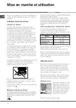
Page 22: ...onsommation de gaz utilisez des casseroles à fond plat munies de couvercle et d un diamètre adapté au brûleur Mise en marche et utilisation Brûleur ø Diamètre récipients cm Rapide R 24 26 Semi Rapide S 16 20 Auxiliaire A 10 14 Pour distinguer le type de brûleur reportez vous aux dessins figurant dans le paragraphe Caractéristiques des brûleurs et des injecteurs Pour les modèles équipés d une grill...

Page 23: ...formation de fumée Le gril étant équipé d un dispositif de sécurité de flamme il faut pousser sur le bouton du FOUR pendant environ 6 secondes En cas d extinction accidentelle de flamme éteignez le brûleur et attendez au moins 1 minute avant de tenter de rallumer Lors de l utilisation du gril garder la porte du four entrebâillée en plaçant le déflecteur D voir figure entre la porte du four et le t...

Page 24: ...âteaux Biscuits Tarte Tartes salées Gâteaux levés 0 5 1 1 1 1 3 3 3 3 15 15 15 15 180 180 180 180 30 35 30 35 45 50 35 40 Cuisson au gril Côtes de veau Côtelettes Hamburgers Maquereaux Croque monsieur 1 1 5 1 1 n 4 4 4 3 4 4 5 5 5 5 5 15 20 20 20 30 15 20 2 4 Cuisson au gril avec tournebroche Veau à la broche Poulet à la broche 1 2 5 5 70 80 70 80 Cuisson au gril avec tournebrochettes Brochettes d...

Page 25: ...tance Ne posez pas d objets lourds sur la porte du four ouverte S assurer que les enfants ne jouent pas avec l appareil Cet appareil n est pas prévu pour être utilisé par des personnes y compris les enfants dont les capacités physiques sensorielles ou mentales sont réduites ou des personnes dénuées d expérience ou de connaissance sauf si elles ont pu bénéficier par l intermédiaire d une personne r...

Page 26: ... de la porte du four S il est abîmé adressez vous au service après vente le plus proche de votre domicile Mieux vaut ne pas utiliser le four tant qu il n est pas réparé Entretien robinets gaz Il peut arriver qu au bout d un certain temps un robinet se bloque ou tourne difficilement Il faut alors le remplacer Cette opération doit être effectuée par un technicien agréé par le fabricant Remplacement ...

Page 27: ...ssible de fermer complètement la porte pour faire fonctionner le four AVERTISSEMENT Le four ne doit pas etre utilisé en verre enlevé AVERTISSEMENT Réassembler le correctement afin que le signe sur le verre est lisible avec la porte du four verre correctement AVERTISSEMENT Le four ne doit pas etre utilisé en verre enlevé AVERTISSEMENT Réassembler le correctement afin que le signe sur le verre est l...

Page 28: ...FR 09 2013 195110515 01 XEROX FABRIANO ...

Reviews: