51
Cable connection
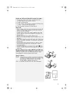
1. Remove the handle on the right side plate of the outdoor unit (one screw).
2. Remove the cable clamp, connect the power connection cable with the terminal on the connecting
board and fasten it. The fitting line distribution must be consistent with the indoor unit.
3. Use cable clamp to fasten the cable connection. For heating and cooling type unit, also use the cable
clamp to fasten the signal control cable, then fasten the corresponding connectors.
4. Confirm the fitting lines are fixed.
5. Install the handle (fastened with one screw).
Notes:
• Improper line connection may cause failure of some electrical components and parts
• When fastening the cable, leave some slack for the cable between the connection point and the fixing point.
Cable Clamp
Power
Connection
Cable
Yellow-Green
Brown
Black
Blue
Handle
Handle
Cable Clamp
Black
Blue
Yellow-Green
Power
Connection
Cable
Power
Connection
Cable
Power
Connection
Cable
Blue
Blue
Black
Black
Yellow-Green
Yellow-Green
Brown
Connection block for outdoor Unit
Connection block for outdoor Unit
Cool/Heat
Model
Diagram
Signal
Control
Cable
AMC 990/1/2
AMC993/4
AMC 996/8
Brown
Black
Blue
Yellow-Green
Power
Connection
Wire
Wire Clamp
Power
Connection
Wire
Indoor Unit terminal board
Outdoor unit terminal board
Blue
Black
Yellow-Green
Brown
Diagram for cooling
and heating unit
Air purging and
leakage test
Connecting diagrams for oudoor and indoor unit
32602005GB.fm Page 51 Thursday, December 14, 2006 11:24 AM

