5 - SET-UP FOR OPERATION
0803_GB_42
- GAS KITCHENS WITH PILOT
04/2008
tool. Rinse and dry.
When reassembling the parts, make sure you place them back in the
right position.
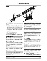
If it is necessary to clean the oven burner (pos. 18 fig. 3) proceed as
follows:
• Remove the lower panel as described previously. Unscrew the
screw fixing the hanger (pos. 2 fig. 3) of the injector-holder (pos.
3 fig. 2), unscrew the screw (pos.5 fig. 2) fixing the burner to the
injector-holder and xtract the injector-holder from its housing;
•
Unscrew the fastening screw (pos. 19 fig. 3) of the burner and
remove it;
• Carefully clean all the holes of the burner with the aid of a tip of
a suitable size;
• Check that the smoke discharge is clear;
• Reinstall everything in reverse order.
After the replacement check the seal using a leack detector spray.
5.3 Replacing parts
All parts must be replaced by authorized technicians
only!
To replace the following parts first remove all the control knobs and
control panel (after loosening the fixing screws), then extract the
ignition wire.
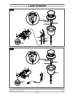
5.3.1 Open flame gas cock
Loosen the fitting of the pipes (pos. 6 and 9 fig. 1) of the gas and of
thermocouple (pos. 8 fig. 1), loosen the fitting (pos. 7 fig. 1) fixing
the cock on the gas piping and replace the piece (pos. 4 fig. 1) install
in reverse order. After the replacement check the seal using a leack
detector spray.
5.3.2 Open flame thermocouple
Loosen the nut (pos. 8 fig. 1) for fastening the thermocouple on the
valve and on the burner (pos. 17 fig. 1) and replace the piece (pos.
14 fig. 1) install in reverse order.
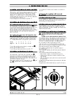
5.3.3 Gas valve gas oven GN 2/1
Loosen the fittings (pos. 1,2,3 and 4 fig. 4) which are for the connec-
tion for the gas pipe and the thermocouple, remove the coil of the
thermostat from its place in the cooking chamber and put in a new
piece in the reverse order. After the replacement check the seal
using a leack detector spray.
5.3.4 Plug gas oven GN 2/1
Unscrew the fastening screws and remove the lower panel, extract
the ignition wire and unscrew the screws (pos. 15 fig. 3), unscrew
the screw (pos. 20 fig. 3) fixing the pilot on the support, pull down
the pilot to a more convenient position and put in a new piece (pos.
16 fig. 3) install in reverse order.
5.3.5 Thermocouple gas oven GN 2/1
Unscrew the screws (pos. 15 fig. 3), the nut (pos. 4 fig. 4) fixing the
thermocouple on the valve and put in a new piece (pos. 14 fig. 3)
install in reverse order.
5.3.6 Main burner gas oven GN 2/1
Remove the front/lower panel by removing the fastening screws.
Unscrew the screws fixing the hanger (pos. 2 fig. 3) of the injector-
holder (pos. 3 fig. 3), unscrew the screw (pos.5 fig. 3) and extract
the injector-holder from its housing, unscrew the screws rear fixing
(pos. 19 fig. 3) of the burner and put in a new piece in the reverse
order. After the replacement check the seal using a leack detector
spray.
5.3.7 Cock solid top
Loosen the fitting of the pipes (pos. 6 fig. 2) of the gas and of ther-
mocouple (pos. 8 fig. 2), loosen the fitting (pos. 7 fig. 2) fixing the
cock on the gas piping and replace the piece (pos. 4 fig. 2) install in
reverse order. After the replacement check the seal using a leack
detector spray.
5.3.8 Plug solid top
Remove the solid top, the flame spreader and the burner body,
unscrew the screw (pos. 18 fig. 2), lift up the support (pos. 17 fig. 2)
pull out the spring using a pointed tool, remove the ignition plug
from the bottom, disconnect the ignition lead and insert a new
plug.
5.3.9 Thermocouple solid top
Loosen the nut (pos. 8 fig. 2) for fastening the thermocouple on the
valve and the screw (pos. 18 fig. 2) of the support (pos. 17 fig. 2)
and replace the piece (pos. 14 fig. 2).
After any maintenance or repair work, replace the con-
trol panel and the lower panel.
After replacing gas input components, check operation
again and test for leakage.
13
· 20
15
14
11
12
13
16
18
19
3
4
2
5
20
Fig. 3

