5 - SET-UP FOR OPERATION
5.1.4 Power check with volumetric method
Using a gas meter and a stopwatch, you can read the volume of gas
output per time unit. The correct volume corresponds to the value
"E" expressed in litres/hour (l/h) or litre/minute (l/min).
The following formula is used to calculate the value of “E”:
It is important measure the power when the appliance is in standby
status.
The calorific power value can be requested from the local gas company.
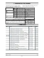
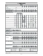
The nominal power and the minimum power with respect to the
nominal pressure are obtained by consulting the table for the
adjustment of the gas passage (table 1).
WARNING
There is no pre-adjustment device for the nominal
power.
5.1.5 Power check for operation with liquid gas
Check if the type of nozzles used meet manufacturer requirements.
Check that the pressure reducer installed in the system has an outlet
pressure which is compliant with paragraph 5.1.2 "Check of power"
(can be checked on the data plate of the appliance or by measuring
the pressure).
E =
Power
Operating calorific value
5.1.6 Check of pilot flame
For proper regulation, the pilot flame must surround the thermo-
couple and it must have a perfect appearance. Otherwise, adjust the
air flow to the pilot.
5.1.7 Checking the primary air
Both the oven and the open flames are equipped with primary air
adjustment.
Air volume flow is correct when there is sufficient protection
against the flame rising when the burner is cold or in case of flash-
back when the burner is hot.
5.1.8 Operation Control
• Start the appliance in accordance with the instructions;
• Check that the appliance does not have any leaks by using a
leak-detecting spray.
• Check ignition and that flame on the main burner lights proper-
ly and is correctly formed, even on low;
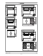
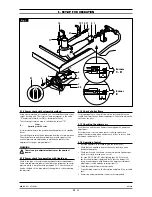
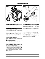
• For oven GN 1/1 (fig. 3B), after lighting (par. 6.3.3), turn the
knob to the minimum (spark) and check that the burner is lit
along its entire length with flames at the lowest possible level.
Adjustments can be made by turning screw (7).
• Check that the pilot flames work properly.
• Copy the setup values on the data plate and place it in a suitable
spot.
• A servicing and maintenance contract is recommended.
020_03
- GAS KITCHENS
12
· 23
03/2006
6
8
7
9
22
5
A
14
17
27
12 13 11
2 1
3
A
C - D
E
4
0
21
Fig. 1
Burners
Burner


