
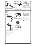
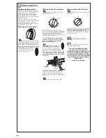

15.
Push in and turn each surface unit
control knob to “LIGHT” position. The flame
should light within 4 seconds. Turn control
knob to “HIGH” position after burner lights.
Check each cooktop burner for proper flame.
The small inner cone should have
a very distinct blue flame 1/4" to
1/2" long. The outer cone is not as
distinct as the inner cone.
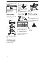
Electronic ignition system
Cooktop and oven burners use electronic
ignitors in place of standing pilots. When a
cooktop control knob is turned to the
“LIGHT” position, the system creates a
spark to light the burner. This sparking
continues until the control knob is turned to
the desired setting.
When the oven control is turned to the
desired setting, a hot surface ignitor heats to
a bright orange and ignites the gas. No
sparking occurs and the glow bar remains
on while the burner operates.
Check operation of cooktop
Page 6
Check operation
E
O
FF
LIG
H
T
H
G
IH
200
300
400
450
OFF
PUSH TO
TURN
BROIL
250
350
500
550
200
300
400
450
OFF
PUSH TO
TURN
BROIL
250
350
500
550
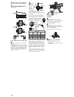
Push in and turn the oven selector control
knob to “350˚F.”
The oven burner should light
in 50-60 seconds; this delay is normal.
The
oven valve requires a certain time before it will
open and allow gas to flow.
Push in and turn the oven selector control knob
to “BROIL.”
The broil burner should light in 50-
60 seconds; this delay is normal.
The oven
valve requires a certain time before it will open
and allow gas to flow.
To avoid damaging the hot surface ignitor,
do Not insert any object into the openings of
the protective shield that surrounds the
ignitor or clean that area.
17.
Check the oven burner for
proper flame.
The flame should be
1/2" long, with inner cone of bluish-
green, and outer mantle of dark blue,
and should be clean and soft in character. No
yellow tips, blowing or lifting of flame should
occur.
If burner does not light, check that the
regulator shutoff valve is in the “on” position
(see Step 11).
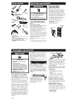
If oven flame needs adjusting:
Locate the air shutter next to the pressure
regulator. Loosen screw and adjust the air
shutter until the proper flame appears. Tighten
screw.
18.
Turn the control knob to “OFF”.
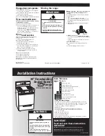
16.
Open broiler drawer to observe
oven burner operation.
air shutter
and screw
regulator
shutoff valve
Check operation of oven burner
20.
Check that the broil burner is
operating.
You have just finished installing
your new range. To get the most
efficient use from your range, read your
Use & Care Guide. Keep Installation
Instructions and Guide close to range
for easy reference. The instructions will
make installing the range in another
home as easy
as the first installation.
21.
Close the broiler drawer. Turn the
oven control knob to “OFF”.
Check operation of broil burner
19.
Broil burner and oven burner are the
same burner.


