

This range is manufactured with white (neutral)
power supply wire and a cabinet-connected bare
ground wire twisted together.
4.
Make electrical connection following the
steps needed for your installation.
1. Disconnect the power supply.
2.
Remove the junction box cover.
3.
Connect range cable to junction box through
the U.L.-listed conduit connector.
4.
Connect the two black wires together with
twist-on connectors.
5.
Connect the two red wires together with
twist-on connectors.
6.
Complete electrical connection according to
local codes and ordinances.
Figure 1
junction
box
red
wires
white
wire
white and bare
ground range
cable wires —
factory crimped
cable from
power supply
black
wires
cable from
range
U.L.-listed
conduit
connector
Figure 2
cable from
power supply
cable from
range
junction
box
U.L.-listed conduit
connector
red
wires
white
wires
black wires
bare ground
wires
If local codes PERMIT
connecting cabinet-ground
conductor to neutral white
wire in junction box:
If local codes DO NOT PERMIT
connecting cabinet-ground
conductor to neutral white
wire in junction box:
If connecting to a
four-wire electrical system:
7.
Connect the factory-crimped
bare and white range cable
wires to the neutral (white) wire
in junction box. See Figure 1.
8.
Replace junction box cover.
7.
Separate the factory-crimped
bare and white range cable
wires.
8.
Connect white range cable wire
to neutral (white) wire in
junction box. See Figure 2.
9.
Connect the bare ground range
cable wire to a grounded wire in
the junction box. See Figure 2.
10.
Replace junction box cover.
7.
Separate factory-crimped bare
and white range cable wires.
8.
Connect white range cable wire
to neutral (white) wire in
junction box. See Figure 2.
9.
Connect the bare ground range
cable wire to the green ground
wire in junction box.
Do Not
connect bare ground wire to
neutral (white) wire in junction
box.
See Figure 2.
10.
Replace junction box cover.
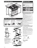
Carefully push against seal area of range front
frame when pushing range into cabinet.
Do Not push against outside edges.
Page 3
10.
Turn on power supply. The display
panel will light up briefly. “PF” should appear in
the temperature display.
Electrical connection
B
Attachment
C
Check operation
D
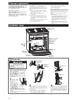
5.
Lift range into cabinet cutout using the
oven opening as an area to grip. Be careful not to
damage countertop.
To avoid damaging the countertop, lift range
slightly while pushing against seal area of front
frame. Push range into cabinet cutout until
shipping feet almost contact cabinet. Use a
Phillips screwdriver to remove screws attaching
shipping feet. Remove and discard shipping
feet.
Push range completely into cabinet and center
range in cabinet cutout. Be careful not to
damage countertop.
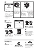
Push trim
into place.
Replace
trim screw.
2 screws
Slide top
of trim up.
9.
Reinstall the oven door by inserting ends
of hinges into hinge slots in the oven frame. Push
hinges in as far as they will go. Open the door (you
will feel the door drop into place) and rotate
both
hinge latches
back to the locked position.
Close and open the door to check that the door
closes and opens completely. If door does not close
or open completely, repeat the door removal step
and reinstall door as described above.
shipping
foot
6.
Important: Securely fasten range to cabinet
using the two screws provided. Insert the screws
through holes in mounting rails. Do Not
overtighten screws.
7.
Slide top end of each trim upward onto
range side rails. Push each trim into place at
bottom of trim. Use screws to attach each trim to
range. Take care not to scratch other surfaces with
ends of trim.
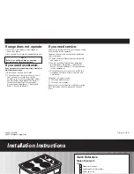
11.
Check the operation of the cooktop
elements.
Push in and turn each surface unit
control knob to “HI” position. Check the operation
of the cooktop elements and indicator lights.
8.
Replace oven racks.
12.
Check the operation of the oven
element.
Press the “BROIL” pad. “BROIL” will
appear in the display. Press the “START” pad.
Make sure the oven door is closed and the “ON”
light is shown in the display area. After 2 minutes,
partially open oven door. You should feel heat
from the oven. Press the “CANCEL” pad.
If your oven does not heat or an “F”, followed by a
number, appears in the display, contact your
dealer or check the “If you need service...” section
of this Installation Instructions.
BAKE
BROIL
CLEAN
Electrical Shock Hazard
Turn power supply off before connecting wires.
Use 8 gauge solid copper wire.
Electrically ground range.
Failure to follow these instructions can result
in death, fire, or electrical shock.
Tip Over Hazard
A child or adult can tip the range and be killed.
Securely attach mounting screws to cabinet.
Reattach mounting screws if the range is
moved.
Failure to follow these instructions can result
in death or serious burns to children and
adults.
WARNING
WARNING
If your house has aluminum wiring, see
“Electrical requirements”, Page 2.


