Page 2
T
O
VE
H
IC
L
E
J
1
8
J
19
J2
0
C
en
C
om
™ C
ore
M
a
i
n
C
ontro
l B
o
x
NOTE: The CANport Communication Board is optional and replaces
the Input Remote Module on Carbide systems.
Preparation:
The following procedure should
be performed with the vehicle
off.
1. Locate your vehicle’s CAN
port. Typically located on the
driver side fender under
hood
(Fig. 1).
2. Locate
the
CAN
port
Interface Cable (included).
This
cable
allows
the
CenCom™ Core system to
communicate
with
your
vehicle’s CAN network.
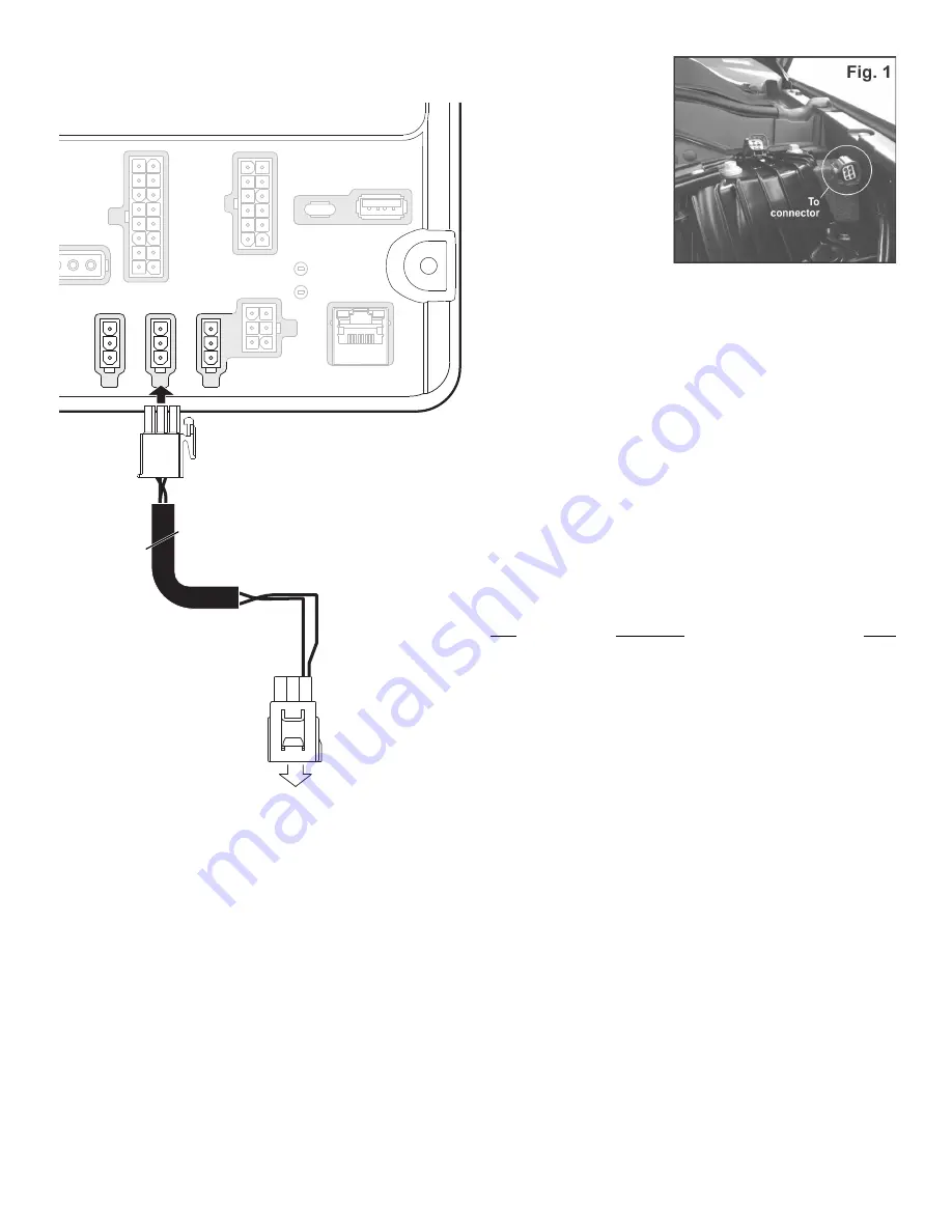
The interface cable is comprised of the following connectors:
• One 6-position YES 2.8 Series Connector male
• One 3 position connector
Connecting to the CANport network:
3. Plug the male YES 2.8 Series Connector onto the vehicle’s CAN port.
4. Plug the interface cable’s 3-position connector into the CAN2 port on
your CenCom™ Core.
The CenCom™ Core system is now connected to the vehicle’s CAN
network. The vehicle’s emission and diagnostic data may now be
accessed
via
the Male Yes 2.8 connector installed earlier in this
installation.
Programming:
Configuring the CenCom Core system to interact with the CANport
network requires a Windows®-based laptop computer. This connection
requires a USB cable and is only needed during the programming
process.
YES 2.8 Series Connector
POS
Description
Color
1..................................Signal - High (CAN 1).......................................BLU
2..................................Signal - Low (CAN 1)....................................... GRY
3..................................N/A
4..................................N/A
5..................................N/A
6..................................N/A
3 Position Connector:
1..................................Signal - High (CAN 1).......................................BLU
2..................................SHIELD .............................................................N/A
3..................................Signal - Low (CAN 1)....................................... GRY


