background image

15


TV

Assembly Instructions for Table-top Display 


Tools required: Hex wrench (provided), Phillips screwdriver, stud finder, pencil, tape measure, power 

drill and 

1/8” drill Bit. 


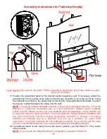
17. Position  the  assembled  stand  at  the  desired  location  against  a  wall.  If  necessary,  adjust  the 

pre-attached Floor Levelers at the bottom of both Legs (D and E) to level the unit. Now, follow 
the instructions printed on the plastic bag containing the Tipping Restraint Hardware to attach 
the tip-over restraint between the Spine and the wall. 

NOTE: 

The tipping restraint hardware included is for wooden stud wall construction. It must be 

attached  to  a  wall  stud.  Depending  upon  your  wall  construction,  different  anchor  hardware 
maybe required. Please contact your local hardware store for assistance. Young children can 
be seriously injured by tipping furniture. You must install the Tipping Restraint  Hardware with 
the  unit to  prevent the  unit  from  tipping,  causing any  accidents  or  damage.  The  tipping 
restraints  are  intended  only  as  a  deterrent,  they  are  not  a  substitute  for  proper  adult 
supervision.  The tipping  restraints  are  not earthquake  restraints.  If you  wish  to add  the  extra 
security of earthquake restraints, they must be purchased and installed separately.


18. The table-top stand is now ready for use. Be sure to position your Flat Panel TV in the center 

of the console. 

NOTE: 

If you choose the Tilting Wall Mount configuration, proceed to PAGE 26. 

Summary of Contents for SM3IN1-5R

Page 1: ...to use this TV Console in different configurations at a later date if desired ADULT ASSEMBLY REQUIRED If you have any questions regarding assembly or if parts are missing DO NOT return this item to th...

Page 2: ...t can provide protection against the unexpected tipping of the unit due to small tremors bumps or climbing The restraint is only a deterrent and is not a substitute for proper adult supervision Use of...

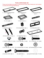
Page 3: ...y 1 D Left Leg Qty 1 E Right Leg Qty 1 F Lower Spine Qty 1 G Upper Spine Qty 1 H Swiveling Bracket Qty 1 I Mounting Frame Qty 1 J Monitor Bracket L R Qty 2 K Cable Wheel Qty 2 L Glass Shelf Qty 2 1 Su...

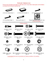
Page 4: ...1 set Inside Plastic Bag TV Mounting Kit AAA M4 x 12 Bolt BBB M4 x 30 Bolt CCC M5 x 12 Bolt DDD M5 x 30 Bolt Qty 4 Qty 4 Qty 4 Qty 4 EEE M6 x 12 Bolt FFF M6 x 35 Bolt GGG M8 x 16 Bolt HHH M8 x 40 Bolt...

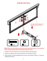
Page 5: ...and fully tighten all bolts This will make the assembly easier 1 Unpack the unit and confirm that you have all the hardware and required parts 2 Locate the Lower Spine F and set back face down on a s...

Page 6: ...6 F B A 3 5 6 Assembly Instructions 4 Fasten the Middle Metal Frame B to the Lower Spine F with two 1 1 4 Bolts 3 and Washers 5 and 6 x 2 x 2 x 2...

Page 7: ...7 Assembly Instructions 5 Fasten the Bottom Metal Frame C to the Lower Spine F with two 1 1 4 Bolts 3 and Washers 5 and 6 F B A 3 5 6 x 2 x 2 x 2...

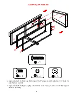
Page 8: ...tach the Right Leg E to Upper Shelf Frames A and B with two 1 1 4 Bolts 3 and Washers 5 and 6 7 Align and attach the Right Leg E to the Bottom Shelf Frame C with one 5 8 Bolt 4 and Washers 5 and 6 x 2...

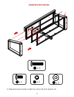
Page 9: ...9 Assembly Instructions 8 Repeat the same procedure to attach the Left Leg D at the opposite end x 1 x 3 x 3 x 2 D A E B C 4 5 6 3 5 6 3 5 6...

Page 10: ...ront edges 10 Secure the Shelf Frames A B and C in place by using six 5 8 Bolts 4 and six Washers 5 and 6 If you choose Table top configuration continue to next step If mounting TV with the Floating S...

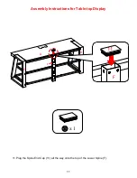
Page 11: ...11 Assembly Instructions for Table top Display 11 Plug the Spine End Cap 11 all the way onto the top of the Lower Spine F x 1 A F E D F 11...

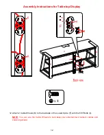
Page 12: ...or Table top Display 12 Attach 2 Cable Wheels K to the backside of the Lower Spine F with the 5 8 Bolts 4 NOTE You can use the Cable Wheels to help keep your entertainment center s cables and cords or...

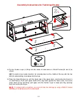
Page 13: ...se into the hole 14 Place the Glass Shelves L with the black side of the glass down onto the Suction Cups 1 on shelf frames Push each glass shelf all the way back against the Spine Also be sure to pre...

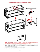
Page 14: ...nel television directly on the top panel Otherwise skip to Step 16 15 Remove the paper backing from the Acrylic Stopper 10 then properly align the acrylic stopper into the cut out on the acrylic stopp...

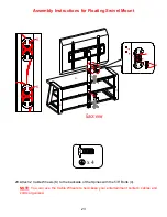
Page 15: ...hed to a wall stud Depending upon your wall construction different anchor hardware maybe required Please contact your local hardware store for assistance Young children can be seriously injured by tip...

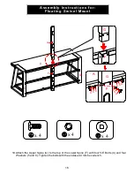
Page 16: ...to the top of the Lower Spine F with four 5 8 Bolts 4 and four Washers 5 and 6 Tighten the bolts with the enclosed 4 mm hex wrench Assembly Instructions for Floating Swivel Mount x 4 x 4 x 4 G F 4 5...

Page 17: ...or Floating Swivel Mount 20 Hold and attach the flat side of the Mounting Frame I onto the Swiveling Bracket H with four 1 2 Bolts 2 and four Washers 5 and 6 Make sure the hex nut and raised holes poi...

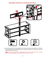
Page 18: ...six 5 8 Bolts 4 and six Washers 5 and 6 Make sure the pivoting bolt head is up Tighten the bolts with the enclosed 4 mm hex wrench NOTE The spine can provide four height options for the TV set Refer...

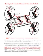
Page 19: ...ately If you are unable to find the correct Bolt consult a local hardware store 23 Follow the appropriate diagram above to attach the Monitor Brackets JL JR to the back of the TV with the selected fas...

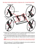
Page 20: ...Bolt consult a local hardware store 25 Follow the appropriate diagram above to attach the Monitor Brackets JL JR to the back of the TV with the selected fasteners Make sure the Monitor Brackets are ve...

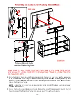
Page 21: ...ask for assistance to lift the television up to hang the Monitor Brackets JL JR onto the Mounting Frame I Set the hooks on the Monitor Brackets over the Mounting Frame and then lower them onto the bar...

Page 22: ...Floating Swivel Mount 28 The Monitor Brackets JL JR can tilt up to 11 downward and 5 upward depending on your optimum viewing position Keep the enclosed 3 16 hex wrench to ensure the tilt adjustment k...

Page 23: ...y Instructions for Floating Swivel Mount 29 Attach 2 Cable Wheels K to the backside of the Spines with the 5 8 Bolts 4 NOTE You can use the Cable Wheels to help keep your entertainment center s cables...

Page 24: ...while twisting it clockwise into the hole 31 Place the Glass Shelves L with the black side of the glass down onto the Suction Cups 1 on shelf frames Push each glass shelf all the way back against the...

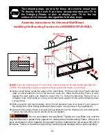
Page 25: ...luded is for wooden stud wall construction It must be attached to a wall stud Depending upon your wall construction different anchor hardware maybe required Please contact your local hardware store fo...

Page 26: ...to at least 2 inch deep on the 4 drill points While holding the Bracket Plate in place loosely screw in the Lag Bolts 8 36 Secure the Mounting Frame I to wall with Lag Bolts 8 and the Washers 9 at th...

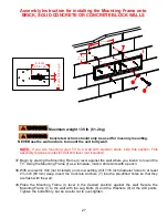
Page 27: ...drill not included on its low setting drill 7 16 inch diameter holes to at least 2 inch 63 mm deep Insert the Concrete Anchors 7 into the pre drilled holes so that they are flush with the wall 39 Pla...

Page 28: ...I Set the hooks on Monitor Brackets over the Mounting Frame and then lower them onto the bars of the Mounting Frame Proceed to center the television 42 When the TV is in its intended position tighten...

Page 29: ...humidity changes can cause fading warping shrinking and splitting of wood It is advised to keep furniture away from direct sunlight as sun may damage the finish Proper care and cleaning at home will e...

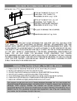
Page 30: ...ed the maximum size and weight of the TV shown in the instructions Be sure to refer to the TV warning label as shown in the instructions Overloading drawers and shelves may result in furniture that ca...

Page 31: ...solamente la que se recomienda para la opci n que escogio ENSAMBLE REQUERIDO POR ADULTO Si tienen alguna pregunta acerca del ensamble o si alguna parte est faltante no retorne este producto a la tien...

Page 32: ...e as sacudidas golpes o en caso de subirse en ella Este restrictor de movimiento solo sirve como medida preventiva y no sustituye la supervisi n por parte de un adulto El uso de este tipo de equipos n...

Page 33: ...E Pata derecha Cant 1 F Poste inferior Cant 1 G Poste superior Cant 1 H Soporte del pivote Cant 1 I Marco de montaje Cant 1 J Soporte de monitor L R Cant 2 K Gu a de cable Cant 2 L Repisa de vidrio Ca...

Page 34: ...Montaje TV AAA Perno de 4x12 mm BBB Perno de 4x30 mm CCC Perno de 5x12 mm DDD Perno Cant 4 Cant 4 Cant 4 de 5x30 mm Cant 4 EEE Perno de 6x12 mm FFF Perno de 6x35 mm GGG Perno de 8x16 mm HHH Perno Can...

Page 35: ...re completamente todos los pernos sto lo har m s f cil durante el ensamblaje 1 Desempacar la unidad y confirmar que se tiene todo el material de ferreter a y partes requeridas 2 Localizar el poste inf...

Page 36: ...6 F B A 3 5 6 Instructivo de ensamblaje 4 Sujetar los repisa intermedia B al poste inferior F con 2 pernos de 1 1 4 3 y arandelas 5 y 6 x 2 x 2 x 2...

Page 37: ...7 F A C B 3 5 6 Instructivo de ensamblaje 5 Sujetar los repisa inferior C al poste inferior F con 2 pernos de 1 1 4 3 y arandelas 5 y 6 x 2 x 2 x 2...

Page 38: ...djuntar la pata derecha E a los repisas superior A y B con 2 pernos de 1 1 4 3 y arandelas 5 y 6 7 Alinear y adjuntar la pata derecha E a los repisa inferior C con 1 perno de 5 8 4 y arandelas 5 y 6 x...

Page 39: ...9 Instructivo de ensamblaje 8 Repetir el mismo procedimiento para adjuntar la pata izquierda D al otro lado x 1 x 3 x 3 x 2 D A E B C 4 5 6 3 5 6 3 5 6...

Page 40: ...ntales 10 Asegurar el repisa inferior A B y C en su lugar usando 6 pernos de 5 8 4 y 6 arandelas 5 y 6 Si elige la configuraci n de pantalla de mesa continue al siguiente paso Si monta la pantalla a l...

Page 41: ...11 Instructivo de ensamblaje para la consola tipo mesa 11 Enchufar la tapa del poste 11 en la parte superior de mismo poste inferior F x 1 A F E D F 11...

Page 42: ...consola tipo mesa 12 Adjuntar 2 gu as de cable K al lado posterior del poste inferior F con los pernos de 5 8 4 NOTA Usted puede usar las gu as de cable para mantener los cables del centro de entreten...

Page 43: ...ntras gira hacia la derecha en el agujero 14 Coloque los repisas de vidrio L con la parte negra del mismo apuntando hacia abajo a las ventosas 1 hacia las repisas Empujar los vidrios completamente hac...

Page 44: ...el panel superior De lo contrario vaya al Paso 16 15 Retire la cinta de la parte inferior del tope de acr lico 10 y luego alinear correctamente el acr lico en el recorte en la plantilla para el acr l...

Page 45: ...debe sujetar a un barrote de pared Dependiendo de la construcci n de su pared es posible que se requiera ferreter a diferente P ngase en contacto con su ferreter a local para obtener ayuda Ni os peque...

Page 46: ...rte superior del poste inferior F con los tornillos de 5 8 4 y cuatro arandelas 5 y 6 Apretar los tornillos con la llave hexagonal de 4 mm Instructivo de Ensambl aje para Flotador giratorio x 4 x 4 x...

Page 47: ...atorio 20 Mantenga y coloque el lado plano del marco de montaje I en el soporte giratorio H utilizando cuatro tornillos de 1 2 2 y cuatro Arandelas 5 y 6 Aseg rese de que La tuerca hexagonal y los agu...

Page 48: ...superior G con 6 pernos de 5 8 4 y las arandelas 5 y 6 Asegurar de que la cabeza del perno especial est arriba Apretar los pernos con la llave hexagonal de 4 mm NOTA El poste puede proveer 4 opciones...

Page 49: ...e Si no encuentra el tornillo adecuado dir gase a su tienda de ferretera local para el mismo 23 Cuando determine el di metro correcto del tornillo a utilizar siga el diagrama apropiado de abajo asegur...

Page 50: ...e a su tienda de ferretera local para el mismo 25 Cuando determine el di metro correcto del tornillo a utilizar siga el diagrama apropiado de abajo asegure el tornillo corto y arandelas junto con el s...

Page 51: ...talla pedir asistencia para levantar la pantalla para adjuntar los soportes de monitor JL JR en el marco de montaje I Poner los garfios de los soportes sobre el marco y enganchelos hacia las barras de...

Page 52: ...del marco flotante 28 Los soportes de monitor JL JR pueden inclinarse hasta 11 para abajo y 5 para arriba dependiendo de su posici n de mayor visi n Mantener la llave hexagonal de 3 16 para asegurar d...

Page 53: ...montura del marco flotante 29 Adjuntar 2 gu as de cable K al lado posterior del postes con los pernos de 5 8 4 NOTA Usted puede usar las gu as de cable para mantener los cables del centro de entreteni...

Page 54: ...la Llave hexagonal mientras gira hacia la derecha en el agujero 31 Coloque los repisas de vidrio L con la parte negra del mismo apuntando hacia abajo a las ventosas 1 hacia las repisas Empujar los vi...

Page 55: ...imiento se incluye para la construcci n de pared con vigas de madera Se debe sujetar a un barrote de pared Dependiendo de la construcci n de su pared es posible que se requiera ferreter a diferente P...

Page 56: ...rticales de referencia que dibujo 35 Con un taladro no incluido perforar agujeros de 3 16 pulgadas de di metro al menos 2 pulgadas de profundo en los 4 puntos Mientras mantiene la placa soporte en su...

Page 57: ...a potencia perforar agujeros de 7 16 pulgadas de di metro de al menos 2 pulgadas 63 mm de profundo Insertar las anclas de concreto 7 en los agujeros pre perforados para que est n a nivel con la pared...

Page 58: ...soportes sobre el marco y enganche en las barras del marco Proceder a centrar la pantalla 42 Una vez que la pantalla est en posici n apretar ambos pernos de bloqueo con el desarmador estrella largo ha...

Page 59: ...mmendable mantener la unidad lejos del sol directo ya que puede da ar el acabado Cuidados adecuados y limpieza pueden extender la vida til de su unidad Siga estas recomendaciones y mantendr su mueble...

Page 60: ...n las instrucciones Aseg rese de consultar la etiqueta de aviso de la TV mostrada en las instrucciones Sobrecargar los cajones y repisas puede resultar en muebles que se rompen o hunden o se in volque...

Reviews: