Whalen LEVELUP SPLS-LTCGD Assembly Instructions Manual Download Page 8


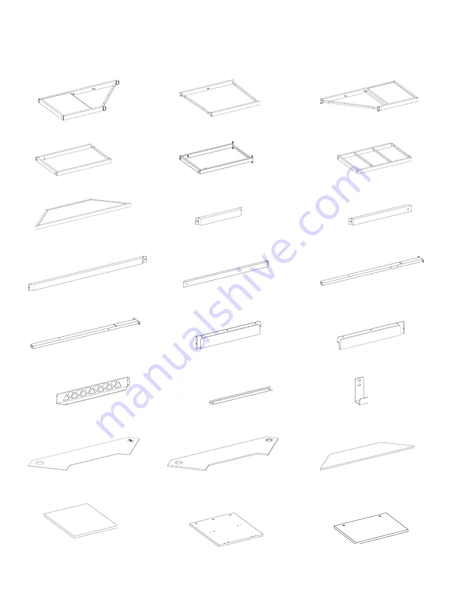
Parts and Hardware List 


Please read completely through the instructions and verify that all listed parts and hardware are present 
before beginning assembly. 


A- Left Top Frame (Qty. 1)                   B- Corner Top Frame (Qty. 1)                  C- Right Top Frame (Qty. 1)     


D- Left Outer Frame (Qty. 1)                 E- Left Middle Frame (Qty. 1)                    F- Right Side Frame (Qty. 1) 


G- Hutch Top (Qty. 1)               H- Left Back Short Stretcher (Qty. 1)         I- Left Back Long Stretcher (Qty. 1) 


J- Middle Back Stretcher (Qty. 1)          K- Right Back Stretcher (Qty. 1)                 L- Corner Left Post (Qty. 1)    


M- Corner Right Post (Qty. 1)          N- Left Cord Management (Qty. 1)      O- Right Cord Management (Qty. 1) 


P- Middle Cord Management (Qty. 1)         Q- Light Support (Qty. 1)


R- Accessory Hook (Qty. 1) 


S- Corner Mouse Pad (Qty. 1)         T- Corner Front Top Panel (Qty. 1)


U- Corner Back Top Panel (Qty. 1) 


V- Left Bottom Panel (Qty. 1)                W- Right Inner Panel  (Qty. 1)


X- Right Shelf (Qty. 2) 

Summary of Contents for LEVELUP SPLS-LTCGD

Page 1: ...are missing DO NOT return this item to the store where it was purchased Please call our toll free customer service number and have your instructions and parts list ready to provide the model name part...

Page 2: ...o the pre drilled large hole in the panel Make sure the arrow on the Cam Lock is pointed towards the Cam Bolt 3 Once the Cam Bolt is connected inside the Cam Lock take a Phillips screwdriver not inclu...

Page 3: ...or Selecting Functions 1 Turn On Standby Press this key to turn on unit or switch to standby mode At power on Unit will automatically turn on and restore to previous status 2 9 Dynamic Mode Adjust Swi...

Page 4: ...te please repeat the Pairing New Remote operation 4 Switch Output Color Sequence The controller s default output signal sequence is Common Green Red Blue If the LED application is in different cable s...

Page 5: ...he AC adapter out with wet hands ensure the safety and integrity of the adapter 3 Do not let the dust or other things accumulate on the product and the AC adapter 4 Do not use the product outside the...

Page 6: ...te can be taken away red light is on again enters the standby status The fourth product features 1 Main functions wireless charging transmitter 2 Standard version WPC 1 2 3 3 Products applicable all w...

Page 7: ...appears to happen check to make sure the battery is installed correctly and try again WARNING Do not ingest batteries 1 Non rechargeable batteries are not to be recharged 2 Batteries are to be insert...

Page 8: ...me Qty 1 G Hutch Top Qty 1 H Left Back Short Stretcher Qty 1 I Left Back Long Stretcher Qty 1 J Middle Back Stretcher Qty 1 K Right Back Stretcher Qty 1 L Corner Left Post Qty 1 M Corner Right Post Qt...

Page 9: ...4 1 extra Qty 10 1 extra 4 Lock Washer 5 Flat Washer 6 Hex Nut Qty 28 1 extra Qty 28 1 extra Qty 2 1 extra 7 Cam Lock 8 Cam Tapping Bolt 9 Cam Bolt Qty 7 1 extra Qty 4 1 extra Qty 3 1 extra 10 M8 x 30...

Page 10: ...sembly easier 1 Unpack the unit and confirm that you have all the hardware and required parts Assemble the unit on a carpeted floor or the empty carton to avoid any scratch 2 Attach the Left Outer Fra...

Page 11: ...t holes as a guide fasten the Left Bottom Panel V to the Left Frames D and E with four 12 mm Screws 11 5 Stand the assembled unit upright 6 Attach the Left Back Short Stretcher H to the Left Frames D...

Page 12: ...cher I to the Left Middle Frame E with one 12 mm Bolt 1 and the Washers 4 and 5 8 Attach the Corner Left Post L to the Left Top Frame A and the Left Back Long Stretcher I with three 32 mm Bolts 3 and...

Page 13: ...Phillips screwdriver DO NOT overtighten the Cam Bolts NOTE Screw in cam bolts must be screwed down flush 10 Securely screw the Cam Tapping Bolts 8 into the designated small holes on the Right Inner P...

Page 14: ...g 11 Attach the Right Side Frame F to the Right Top Frame C with two 32 mm Bolts 3 and two Washers 4 and 5 12 Attach the Right Inner Panel W to the Right Top Frame C by engaging the Cam Locks 7 Refer...

Page 15: ...the Right Inner Panel W by engaging four Cam Locks 7 and four 30 mm Wood Dowels 10 Refer to page 3 on Cam Lock system operation supplement 14 Secure the Right Shelves X to the rails of the Right Side...

Page 16: ...p Frame C with two 32 mm Bolts 3 and two Washers 4 and 5 17 Fasten the Right Back Stretcher K to the Corner Right Post M with the 32 mm Bolt 3 and the Washers 4 and 5 18 Secure the Right Back Stretche...

Page 17: ...e B onto the U shaped brackets on the Top Frames A and C and fasten them into place with four 12 mm Bolts 1 20 Fasten the Corner Top Frame B to the Top Frames A and C with four 25 mm Bolts 2 and four...

Page 18: ...embling 21 Attach the Middle Back Stretcher J to the Left and Right Posts L and M with two 12 mm Bolts 1 and two Washers 4 and 5 22 Position the Corner Top Panels T and U onto the top of the assembled...

Page 19: ...ils of Top Frames A and C with six 25 mm Screws 12 24 Secure the Corner Top Panels T and U to the metal tabs with eight 12 mm Screws 11 25 Using the pilot holes as a guide Attach the Metal Bracket 13...

Page 20: ...les as a guide Attach two Cord Clips 14 to the Top Panels T and U with two 12 mm Screws 11 in each 27 Attach the Hutch Top G to the Left and Right Posts L and M with four 12 mm Bolts 1 and four Washer...

Page 21: ...e Left Side assembly with five 12 mm Bolts 1 29 Secure the Right Cord Management O to the Right Side assembly with five 12 mm Bolts 1 30 Attach the Middle Cord Management P to the Left and Right Posts...

Page 22: ...Management P with two 12 mm Bolts 1 and two Hex Nuts 6 Note Ensuring that the light function properly This can be done by moving the Light Support Q forward and back 32 Attach the Buckles Y to the Lig...

Page 23: ...es Y 34 Feed the wire of Wireless Charger Z through the cutout of the Desk Top and push into the cutout from top of Desk Top ensuring the wire are not pinched NOTE You can use the Cord Clips to help k...

Page 24: ...Fixture together properly Secure the cord in place with plastic ties Make sure the loose connecting wire is taped securely and out of the way Connect the light fixture to the power transformer Refer...

Page 25: ...37 Attach the Accessory Hook R to the Left Top Frame A with two 12 mm Bolts 1 38 Position the unit at the desired location against a wall If necessary adjust the Floor Levelers at the bottom of the f...

Page 26: ...ts screws periodically and tighten them if necessary Further Advice about Wood Furniture Care It is best to keep your furniture in a climate controlled environment Extreme temperature and humidity cha...

Reviews: