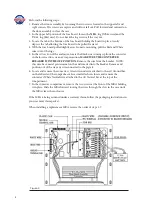
Perform the following steps:
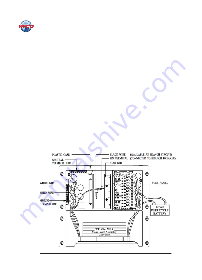
1. Remove the door assembly by loosening the two screws located in the upper left and
right corners. The screws are captive and will not fall out. Pull forward and outward on
the door assembly to clear the case.
2. In the upper left portion of the fuse board, loosen the
NEG-
lug (White wire) and the
VCC+
lug (Red wire). Do not back the lug screws all the way out.
3. Locate the tab at the bottom of the fuse board holding the board in place. Gently
depress the tab allowing the fuse board to be pulled forward.
4. With the fuse board pulled slightly away from its mounting, pull the Red and White
wires out of the lugs.
5. In the AC section of the enclosure, locate the Black wire coming up from the converter
in the lower section. As an extra precaution,
MAKE SURE THE CONVERTER
BREAKER IS IN THE OFF POSITION
. Remove the wire from the breaker. NOTE:
this wire has a metal pin terminal on the end inserted into the breaker. Remove and
position out of the way any wire connected to the pigtail.
6. Locate and remove the converter’s Green Ground wire attached to the AC Ground bar
on the left side of the compartment. In a similar fashion, locate and remove the
converter’s White Neutral wire attached to the AC Neutral bar at the top of the
compartment.
7. In the converter compartment, remove the two screws at the front of the MBA holding
it in place. Slide the MBA forward routing the wires through the slots in the case until
the MBA clears the enclosure.
If the MBA is being returned under a warranty claim, follow the packaging instructions in
your warranty claim packet.
When installing a replacement MBA, reverse the order of steps 1-7.
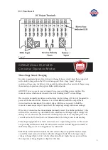
Figure 4
8
Summary of Contents for WF-8900MBA Series
Page 11: ...Figure 5 11 ...


