


2
ETL-ES-Panorama-WH08
1. Installation work and electrical wiring must be done by qualified person(s) in accordance with all applicable codes and standards (ANSI/NFPA 70-1999), including
fire-rated construction.
2. Use this unit only in the manner intended by the manufacturer. If you have any questions contact the manufacturer.
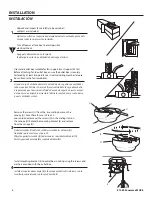
3. After making the wire connections, gently push connections into outlet box with wire nuts pointing up. The wires should be spread apart with the grounded
conductor and the equipment-grounding conductor on one side of the outlet box and ungrounded conductor on the other side of the outlet box.
4. Before you begin installing the fan, switch power off at service panel and lock service disconnecting means to prevent power from being switched on accidentally.
When the service disconnecting means cannot be locked, securely fasten a prominent warning device, such as a tag, to the service panel.
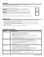
5. Be cautious! Read all instructions and safety information before installing your new fan. Review the accompanying assembly diagrams.
6. When cutting or drilling into wall or ceiling, do not damage electrical wiring and other hidden utilities.
7. Make sure the installation site you choose allows the fan blades to rotate without any obstructions. Allow a minimum clearance of 7 feet from the floor to the
trailing edge of the blade.
8. To reduce the risk of fire, electric shock, or personal injury, this fan must be mounted to an outlet box marked suitable for fan support, and use the mounting screws
provided with the outlet box. (Mounting must support at least 35 lbs.)
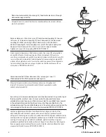
9. WARNING! Do not bend blade holders during installation to motor, balancing or during cleaning. Do not insert foreign object between rotating blades.
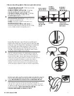
10. Attach the mounting bracket using only the hardware supplied with the outlet box. Fan is only to be mounted to an outlet box marked “Acceptable for Fan Support”.
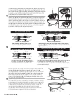
11. WARNING! To reduce the risk of fire or electric shock, do not use this fan with any solid state fan speed control device, or variable speed control.
12. If this unit is to be installed over a tub or shower, it must be marked as appropriate for the application.
13. NEVER place a switch where it can be reached from a tub or shower.
14. The combustion airflow needed for safe operation of fuel-burning equipment may be affected by this unit’s operation. Follow the heating equipment
manufacturer’s guideline safety standards such as those published by the National Fire Protection Association (NFPA), and the American Society for Heating,
Refrigeration and Air Conditioning Engineers (ASHRAE) and the local code authorities.
15. Before servicing or cleaning unit, Switch power off at Service panel and lock service disconnecting means to prevent power from being switched on accidentally.
When the service disconnecting means cannot be locked, securely fasten a prominent warning device, such as a tag, to the service panel.
16. All set screws must be checked and re-tightened where necessary before installation.
17. WARNING! Lamps included in this ceiling fan should not be used with any dimming system. To reduce the risk of fire, electric shock or personal injury,
do not use dimmers.
SafETy TiPS /
CoNSejoS de SeGuridad
OBSERVE THE FOLLOWING: READ AND SAVE THESE INSTRUCTIONS /
HAGA LO SIGUIENTE: LEA Y GUARDE ESTAS INSTRUCCIONES
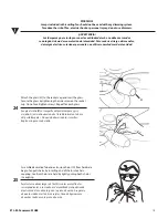
WaRNiNG: TO REDUCE THE RiSK Of fiRE, ELECTRiC SHOCK, OR PERSONaL iNJURy, MOUNT TO OUTLET BOX MaRKED "aCCEPTaBLE fOR faN
SUPPORT", aND USE THE OUTLET SCREWS PROViDED WiTH THE OUTLET BOX. MOST OUTLET BOXES COMMONLy USED fOR THE SUPPORT Of
LiGHTiNG fiXTURES aRE NOT aCCEPTaBLE fOR faN SUPPORT aND May NEED TO BE REPLaCED. CONSULT a QUaLifiED ELECTRiCiaN if iN DOUBT.
adVerTeNCia: Para reduCir eL rieSGo de iNCeNdio, deSCarGa eLÉCTriCa o LeSioNeS PerSoNaLeS, MoNTe eL VeNTiLador eN uNa Caja de eMBuTir roTuLada
“adeCuada Para VeNTiLadoreS”, Y uTiLiCe LoS TorNiLLoS de MoNTaje iNCLuidoS CoN La Caja de eMBuTir. La MaYorÍa de LaS CajaS de eMBuTir uTiLiZadaS
NorMaLMeNTe Para arTeFaCToS de iLuMiNaCiÓN No SoN adeCuadaS Para VeNTiLadoreS Y deBerÍaN Ser reeMPLaZadaS. Si TieNe PreGuNTaS, CoNSuLTe a uN
eLeCTriCiSTa CerTiFiCado.
1. El trabajo de instalación y el cableado eléctrico los deben efectuar personas calificadas cumpliendo con todos los códigos y las normas aplicables (ANSI/NFPA 70-1999), incluyendo
las de incendio.
2. Use esta unidad sólo de la manera en que el fabricante quiere que se haga. Si tiene dudas, llame al fabricante.
3. Después de hacer las conexiones, empuje con cuidado las conexiones dentro de la caja de empalmes con los conectores de cables mirando hacia arriba. Se deben separar los cables:
el conductor de puesta a tierra y el conductor de puesta a tierra del equipo a un lado de la caja de embutir, y el conductor que no tiene puesta a tierra del otro lado de la misma.
4. Antes de comenzar a instalar el ventilador, apague la alimentación en el panel de servicio y bloquee el medio de desconexión del servicio para evitar que se encienda accidentalmente.
Cuando no se puede bloquear el medio de desconexión del servicio eléctrico, fije de manera segura y un dispositivo de advertencia prominente, como un rótulo, al panel de servicio.
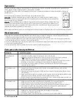
5. ¡Tenga cuidado! Lea todas las instrucciones y la información de seguridad antes de instalar su ventilador nuevo. Revise los diagramas de montaje incluidos.
6. Al cortar o perforar una pared o el cielo raso, no dañe el cableado eléctrico y otras instalaciones de servicios públicos ocultos.
7. Asegúrese de que el sitio para la instalación que escoja permita que el ventilador gire libremente sin obstrucciones. Deje un espacio mínimo de 7 pies desde le piso hasta el borde
posterior de la paleta.
8. Para reducir el riesgo de incendios, choques eléctricos o lesiones personales, este ventilador se debe montar sobre una caja de embutir que tenga una marca que indique que es
adecuada para soportar un ventilador. Además debe utilizar los tornillos correspondientes incluidos con la caja de embutir. (El montaje debe soportar por lo menos 15.87 kgs.)
9. ¡ADVERTENCIA! No doble los soportes para las paletas durante la instalación al motor, al balancear o durante la limpieza. No inserte objetos extraños entre las paletas mientras giran.
10. Fije el soporte de montaje usando sólo la tornillería suministrada con la caja de embutir. El ventilador sólo se debe montar en una caja de embutir marcada “Acceptable for Fan
Support” (Aceptable para soportar ventiladores).
11. ¡ADVERTENCIA! Para reducir el riesgo de incendios o choques eléctricos, no use este ventilador con un dispositivo de control de velocidad de estado sólido para ventilador,
o un control de velocidad variable.
12. Si esta unidad se instalará sobre una bañera o una ducha, debe estar identificada como adecuada para ese tipo de aplicación.
13. NUNCA coloque un interruptor donde se pueda alcanzar desde una bañera o una ducha.
14. Es posible que la operación de esta unidad afecte el flujo de aire de combustión necesario para la operación segura de equipo que quema combustible. Siga la directrices de seguridad del
fabricante de equipo de calefacción como las publicadas por la Asociación Nacional de Protección Contra Incendios (National Fire Protection Association, NFPA), y la Sociedad Americana
para Ingenieros de Calefacción, Refrigeración y Aire Acondicionado (American Society for Heating, Refrigeration and Air Conditioning Engineers, ASHRAE) y las autoridades del código local.
15. Antes de efectuar tareas de servicio o limpieza en la unidad, apague la alimentación en el panel de servicio y bloquee el medio de desconexión del servicio para evitar que se encienda
accidentalmente. Cuando no se puede bloquear el medio de desconexión del servicio eléctrico, fije de manera segura y un dispositivo de advertencia prominente, como un rótulo, al
panel de servicio.
16. Antes de realizar la instalación, es importante comprobar y volver a ajustar todos los tornillos, según corresponda.
17. ¡ADVERTENCIA! Las lámparas que se incluyen con este ventilador de techo no deben ser usadas con ningún sistema de conmutación de intensidad. Para reducir
el riesgo de incendios, descargas eléctricas o lesiones personales, no utilice conmutadores de intensidad.
PREPaRaTiON /
PreParaCiÓN
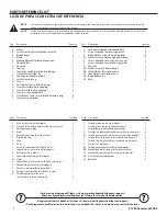
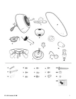
Before beginning assembly, installation or operation of product, make sure all parts are present. Compare parts with the Parts Reference List.
Estimated Assembly Time: 35 minutes (standard installation) Tools Required for Assembly: Phillips Screwdriver, Step Ladder. (not included)
Antes de comenzar el montaje, la instalación o la operación de este producto, compruebe que contenga todas las piezas requeridas. Asegúrese de que las piezas
corresponden a la Lista de piezas con letras de referencia.
Tiempo estimado de montaje 35 minutos (instalación estándar) Herramientas necesarias para el montaje: Destornillador Phillips y escalera de mano (no incluidos)