TYPE KQS PHASE SELECTOR RELAY
.(eJ0-32
.SCREW.S
/"OR TERMIA.IAW
if
DOl, M
T4. J.IOL£S
(-4-HDLE:S)
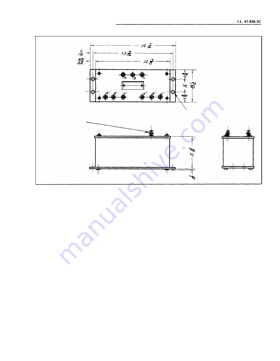
Fig. 4. Outline and Drilling Plan for Type KQS Negative Sequence Filters.
2-D-1707
7
www
. ElectricalPartManuals
. com
Page 1: ...e mounting structure for the magnetic core The magnetic core which houses the lower pin bearing is secured to the frame by a locking nut The bearing can be replaced if neces sary without having to rem...
Page 2: ...en above 2 The negative sequence coils of the type KQS re lay are normally connected in star to terminals A B and C of the negative sequence filter The neu tral of this star should not be grounded The...
Page 3: ...the underside of the bridge and is held in place by a spring type clamp that does not have to be loosened prior to making the necessary adjustments The spring is to be adjusted such that the contacts...
Page 4: ...tral made by connecting terminals A B and C together the voltage across the re lay terminals 2 and 3 4 and 5 and 6 and 7 should be zero Now reverse the connections to the filter in 4 put terminals A a...
Page 5: ...LECTOit COITACTS CLOS R M FROIT VIEW INTERNAL SCHEMATIC X3 IMDICATIMG COMTACTOit SWITCH ZERO SEQUUCE COILS CHASSIS OPERATED SHOitTia SWITCM ifi r CURlEIT TEST JACI __Q_j 9 TERM I MAL 187A421 Fig 1 Int...
Page 6: ...NOT CURRENT FORCED CIRCUIT MAY BE OPENED WITHOUT DISCONNECTING C T S NOTE 3 THIS POINT SHOULD NOT BE GROUNDED NOTE 4 USED FOR KD 10 RELAYS 3 PHASE UNIT CON NECTIONS 876A759 0 Fig 2 AC External Connect...
Page 7: ...L _ 4 1 9 2 8 1C eJ0 32 SCREW S OR TERMIA IAW ttt 3T I I f f if DOl M T4 J IOL S 4 HDLE S Fig 4 Outline and Drilling Plan for Type KQS Negative Sequence Filters 2 D 1707 7 w w w E l e c t r i c a l P...
Page 8: ...USE 5 18 STUD 16 190 32 SCREW I 1 J PANEL DRILLIIIG OR PANEL CUTOUT I DRILLING FOR SEMI FWSH I TG CUTOUT FOR PROJECTIQH MTG FROHT VIEW 3 DU 20 HOUS OR CUTOUT i 16 DIA 2 HOL 57D7905 Fig 5 Outline and...