55
Lit. No. 21857
June 15, 2003
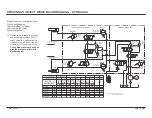
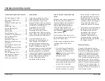
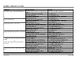
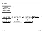
Replace F1. Go to condition “Control
F1 Fuse Blows” in General
Diagnostic Table.
NO
Remove and test F2 with ohmmeter.
Is F2 good?
Replace control or proceed by carefully
disconnecting the white coil cord connector
from the PC board. Test the coil cord harness
for continuity between the connectors
according to the electrical schematic. Note
internal connections in the harness. Does
continuity match schematic?
YES
Remove and test F1 with ohmmeter.
Is F1 good?
NO
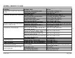
Replace F2. Go to condition “Control
F2 Fuse Blows” in General
Diagnostic Table.
YES
NO
Replace PC board
Replace coil cord
harness.
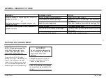
CONTROL TEST
CAUTION
Printed circuit board (PCB) is
subject to damage from static
electricity. Follow instructions
below to safely handle PCB.
To safely handle PCB:
1.
Place control on its side and
remove top half of handle,
leaving the PCB in lower half.
2.
Remove PCB from housing by
only touching the edges of the
PCB.
3.
Touch a clean finger to metal part
of fuse "F2".
4.
PCB is now safe to handle as
long as contact with it is
maintained.
Test Procedure
1. Disconnect the control in the cab
and remove to bench.
2. Remove control handle half to
access internal components.
3. Refer to diagram for fuse location.
NOTE: Fuse F1 is for motor relay,
S1, S2 and S3 solenoid coils.
Fuse F2 is for S4, S5 and S6
solenoid coils.
F1
F2
FUSES


