


Westrn Reserve Controls
WRC-CANR-DF-DN User’s Manual
PUB 14.1
1
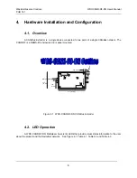
1. Overview
The WRC-CANR-DF-DN Fiber Optic CAN Bus Extender converts a copper cable medium CAN-Bus
network to a fiber optic medium. The WRC-CANR-DF-DN is always used in pairs and, along with the fiber
optic cable set, inserts a length of fiber media into the copper CAN Bus network. It typically is used to
convert a section of the CAN bus to a pair of fiber optic cables. The primary purposes of configuration is to
extend the maximum length defined for one continuous network cable bus and to provide network protection
from external, high-energy electrical interference, such as lightning storms, arc welders, etc. They can be
connected in a bus trunk line or drop line.
The Extenders are transparent to the other nodes on the bus. They receive and actively re-transmit
(store-and-forward) each message received at either side of the network without interpreting the message or
acting upon it. The Fiber Extenders perform all appropriate CAN Bus arbitration on the copper bus as it re-
transmits the message.
The WRC-CANR-DF-DN is a member of WRC’s family of products that extend the system
communications lengths for DeviceNet, SDS (Smart Distributed System) and other CAN, V2.0, Part A,
serial bus systems. By allowing the user to extend the bus length for any given speed, they assist the user
in cost-effectively implementing I/O or other nodes on these buses at remote locations that would be more
difficult or more expensive to do otherwise.
The unit derives its power through the copper network connector on Side A.
1.1. Features
The WRC-CANR-DF-DN has the following features:
•
Extends CAN-Bus cable lengths - trunk line or drop lines
•
Expands the usable applications for CAN-Bus systems
•
Allows operation at higher speeds for specific distances
•
Provides superior electrical interference protection to copper cables
•
Operates at 125K, 250K and 500K baud
•
Autobaud version standard, fixed baud rate optional
•
Automatic speed selection - no configuration required
•
Isolates the two sections of the copper bus
•
Transparent to the Master and Slave devices on the bus
•
No address selection needed
•
No configuration parameters
•
DeviceNet; SDS; CAN, V2.0, Part A compatible
•
Powered from the 24Vdc supplied by bus network or the user
•
Sealed NEMA-4X enclosure
•
Standard round, mini-style connector with male pins for copper cable
•
Standard Fiber Optic ST female connector, 62.5/125um technology
•
Standard CAN chips manage bus error detection
•
Standard CAN chips handle message bus contention
•
Less than 100
µ
sec latency
•
Termination built in on cable side (may be removed by user when appropriate)
•
4 bi-color (red/green) status LEDs


