WC-6 Operating Instructions
3
tolerate heat well, so turning the unit on when in use, and off when not, will ensure a long
service life of the LED Assembly (LED, Printed Circuit Board and Heat Sink).
Over time, the Lens/Filter may become clouded do to the intense UV light. When Clouded
the Operator may notice a reduction in UV Irradiance, but this will become evident with
checking the unit with a Longwave UV Radiometer. Replacement Lens can be ordered
separately, but are not considered a consumable item.
4. Field Characteristics
–
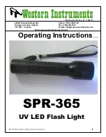
The SPR-365 produces an intense UV illumination area of
approximately 5” (or 120 mm) at a distance of 15” (38cm). The average intensity over this
area is 5,000
ц
W/cm², however the area just outside the center of this area will be higher
than 10,000
ц
W/cm².
5. Maintenance –
After extended use the SPR-365 should be cleaned with a mild soap
solution and thoroughly dried. The unit should be visually inspected for any damage that
could cause harm to the operator, or the material being inspected. Special attention should
be paid to the Push Button Switch Cover, to ensure its fit is acceptable and it is not cracked
or failing in any way.. The most important item is to ensure Oil is not allowed to soak into the
rubber switch cover, which will cause it to harden and crack.
Whether industrial specifications are being observed or not, the LED Flash Light should
be tested periodically, using a calibrated Longwave UV Radiometer to ensure it continues
to have a minimum output of 1,500
ц
W/cm² at 15” (38cm). If the unit fails such a test, first
inspect the Lens to ensure it is not clouded or dirty. If the unit continues to fail, contact
the Distributor or Western Instruments for instructions on corrective action.
6. Battery Charging
–
To charge a SPR-365’s
Nickel–Metal Hydride
Battery, it must be
installed in the Housing, with the Battery End Cap securely tightened to the Body. First
Plug in the charger (100 to 240 VAC / 50 to 60Hz) to mains power. When this is done,
the Red LED will illuminate. When the Charger Connector is plugged into the Battery
Charger Receptacle, the Red LED will turn off and the Green LED will come on. If there is
a fault in the charging system, the Red LED will flash.
The 3.7 Volt / 2600 mAmp-Hour
Nickel–Metal Hydride
Battery will take approximately 3 ½
hours to fully charge. The batteries can be charged at any point of their cycle, but should
not be left on the charger for more than 3 ½ hours at a time. It is recommended the
operator start his day, or an inspection cycle, with both batteries charged., which will take
a little ‘battery management’ on his part.
The SPR-365 can be operated with the charger plugged in, however the battery should
have at least 20% of its capacity in reserve. The SPR-365 should not be used
5” or 120mm


