Western Electric 22E Instruction Bulletin Download Page 12

structions  which  are  a  part  of  the  B-147071 
Set  of  Accessories  for  Battery  operation. 

If 

batteries  only  are  to  be  used,  the  battery  ca­

ble  plug  should  be  plugged  into  the  power 
supply  receptacle  at  the  right  hand  end  of 
the  amplifier. 

AC  and  Battery  Operation 

If  both  a-c  and  battery  supplies  are  to 

be 

used,  the  five-wire a-c  supply  cable  should  be 
plugged  into the  receptacle  at the right hand 
end  of  the  amplifier  unit,  and  the  battery 
supply  cable  plugged  into  Jack  J2  of  the  a-c 

unit.  Selection  of  either  a-c or  battery  opera­

tion  of  the  filaments  and  plates  is  then  made 

by  operating  switch  D3  (plate)  and  switch 
D2  (filament),  both  of  which  are  mounted 

on  the  a-c  power  unit. 

To  turn  on  the  equipment,  connect  the 

power  cord  to  the  a-c  line  and  operate  the 
power  switches  on  both  the  amplifier  and 
the  power  unit.  The  equipment  is  now  ready 
for  operation. 

When  using  batteries,  the  drain  on  the 

batteries  due  to  the  volume  indicator  lights 

is  0.3  ampere.  To  prolong  battery  life,  it  is 
recommended  that the  \IOlume  indicator  lamp 
switch  be  left  OFF  as  much  as  possible.  This 

is  particularly  important  when  dry  batteries 
are  used,  since  the  continuous  use  of  the 

lamps  will  greatly  reduce  battery  life.  Fila­

ment  and  plate  batteries  should  be  changed 

when  the  meter  indicates  voltages  below 
"O  vu"  or  "100"  on  the  scale. 

OPERATION 

Goin  Settin9s 

As  a  general  rule,  the  master  gain  control 

should  be  operated  as  low  as  practicable 
since  this will  result  in  the  minimum  amount 
of  noise.  Enough  latitude  should  be  permit­
ted,  however,  to  allow for variations  in sound 

levels  of  the  program. 
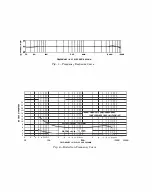
Output  Level 

Normally  an  output  level  of  +8  vu  is  ade­

quate.  In  some  cases,  jt  may  be  necessary  to 

transmit  programs  at  a  higher  level.  The 
22E  Speech  Input  Equipment  will  deliver 

levels  at  +18  vu  without  serious  distortion. 

(See  Figure  2.) 

Precautions 

The  plate  and  filament  voltages  can  be 

checked  while  the  equipment  is  in  operation. 

It  is  recommended  that  a  close check  be  kept 

on  the  condition  of  the  batteries. 

The  output  line  keys  are  so  connected  that 

when  in  the  mid-position  the  program  line 
is  short  circuited.  The  purpose  of  this  is  to 

enable  master  control  to  make  loop  tests 

when  the  remote  location  is  unattended.  In 

the  event  that  more  than  one  pickup  is  made 

from  a  location  where  multiple  extensions 

of  the  program  line  are  used,  the  line  keys 
"hould  not  be  left  in  the  mid-position  since 
this  will  disable  all 

of 

the  line  extensions. 

MAINTENANCE 

Some  tubes  have  higher  noi:;e  level:;  than 

others.  It may  be desirable to  select  tubes for 
the  first  amplifier  stage,  although  the  cush­
ioned  socket  greatly  reduces  trouble  from 

microphonic  noise. 

While  this  equipment  is  rugged  in  con­

struction,  it should  be  afforded  the  degree  of 

maintenance  and  inspection  that  any  high 

quality  equipment  would  ordinarily  require. 

Cleanliness  is  essential  for  best  opera

t

ion 

and  therefore  the  equipment  should  be  kept 
free  of  dust  and  dirt.  Compressed  air  or  a 

soft  bristle  brush  is  recommended  for 
cleaning  the  apparatus.  Potentiometer  con­

tacts  should  occasionally  be  cleaned  with  car­
bon  tetrachloride  and  then  thinly  covered 

with a  good grade  of light mineraLoil.  Excess 

oil  should  be  wiped  off  with  a  lint-free  cloth. 

Summary of Contents for 22E

Page 1: ...Wesrern Electric 22E SPEECH INPUT EQUIPMENT IN S T RUCT I O N BULLET I N N O 1175 I S S UE N O 1...

Page 2: ...siern Electric 22E SPEECH INPUT EQUIPMENT Research and design by Bell Telephone Laboratories INSTRUCTION BULLETIN NO 1175 ISSUE NO I...

Page 3: ...Equipment Furnished a AC Operation b Battery Operation c Both AC and Battery Operation 2 Accessories Required a Cables and Plugs b Batteries c Monitoring d Microphones and Microphone Accessories 3 As...

Page 4: ...INDEX Cont d e Ground f Battery Cable g AC Connection h Power Switches i Plate Current Check 5 Operation a Gain Settings b Output Level c Precautions IV MAINTENANCE 6 6 7 7 7 7 7 7 7 7...

Page 5: ...Case with Cover 0 Ballery compartment with cord nd plug E AC Power Unit with cord nd plug F 639 type Microphone G KS t2COO Transmiller Cover H 24A Tronsmiller Mounting I I IA Trans mitter Allochment J...

Page 6: ...lines 65 db for Battery Operation Both at 70 db net gain and referred to output 62 db for AC Operation signal of 18 dbm Approximately 0 2 J o at 8 dbm 1 5 at 18 dbm See curve Figure 2 Four parallel mi...

Page 7: ...sa as may be required Receptacles and parallel mixing potentiom eters are provided for four microphones A master gain control is incorporated in the 3 stage amplifier Pads for either 150 or 600 ohm ou...

Page 8: ...rmally used for most program lines but the 150 ohm output is frequently used where the mismatch will provide a beneficial equalizing effect tending to compensate for the frequency transmission charact...

Page 9: ...ier A 47 Type Plug and a cord such as the 630 Type are recommended for making con nections between the 22E Amplifier and the monitoring amplifier ES 610199 Power Unit For a c operation the ES 610199 P...

Page 10: ...rage battery operation the required batteries are 4 Eveready No 762S or Burgess No 5308 for plate 1 Exide No 3 AC 7 1 storage battery per DA 26588 For filaments For dry cell battery operation the requ...

Page 11: ...wer Unit or both The B 147071 Set of Accessories for bat tery operation contains all the accessories excepting batteries listed above that are 6 necessary to modify the carrying case Full instructions...

Page 12: ...ould be permit ted however to allow for variations in sound levels of the program Output Level Normally an output level of 8 vu is ade quate In some cases jt may be necessary to transmit programs at a...

Page 13: ...as This enamel may be obtained from the nearest distributor of Western Electric audio facili ties It is supplied with an aluminum powder 8 that is not required for this application Should the 22E Spee...

Page 14: ...es one round and one hexagonal mounting nuts P R Mallory Co 1321 Two Gang Switch Two Circuits 11 Points each Circuit with Shaft IA lg 2 Plain Hex Nuts and 1 Lockwasher Yaxley Manufacturing Co Switch S...

Page 15: ...rying Case per ESR 610264 2 Following Items are Specific to the type of Power Supply For AC Supply Mallory Capacitor 10 10 mf 450 V Type FPO 231 1 dia x 2 lg can Furnish with metal washer A 93403 Mall...

Page 16: ..._ 2 3 4 5 67891 20 100 fRlQU NC IN CYCLES PU SlCO D Fig 1 Frequency Response Curve NOTE 7 500 C l S 2 NO H uM ONLY LINE VOlTAGf 120V 60 CYCU A C 2 OUTPUT LEVEL 18 DBM I I I I I I III OUTPUT LEVEL e DB...

Page 17: ...F C5 0 4MF R2 62QW R3 24QOW C4 0 4MF C 7 0 03MF Rl3 0 24MEG cs 50MF Rl2 s I 620W C6 1 I R2S I I 2 MF r 51ooow DI 5 4 3 I I 2 I T2 17SB I RD RD WH 3 Rl4 Rl5 3300W 2400 I I 0 1 __ e 14 QOFF O OFIL I I 0...

Page 18: ...l 5 CNO OR J Cl I I I I I I 0 c t _ _ I OA L T L d ll l T IT I IleL AO Ct I C7 i j I c wH I I WH rl u I l 1 f 1 l I I I 1 9 i I C2 k t N l I T 0 03 t O 4 I T2 ____ _ l l L 1 ___ c I 0 c r 1 I 11 V I I...

Page 19: ...Tl JI LI L2 llOV A C CORD ANO PLUG TO AMPLIFIER CONTROL UNIT Fig S Power Unit Schematic AC FIL PLATE DC 3 J2 03 4j 06J2 DC...

Page 20: ...v suu r y l D c 0 c liLJ r I RD I I I I I I I I L2 I ______ I _ I I I I I I I I I I LI I __ _ __ _ I GROUND i t i 1 IU W til JI I I I 110 O f VSI F F f __ II II 01 r I 2 4n 1 5 7_ 6 O Tl 0 100 n II a...

Page 21: ...wesrern Electric QUALITY COUNTS...

Reviews: